Rane Sixty-Four Manual
Rane
Blandekonsol
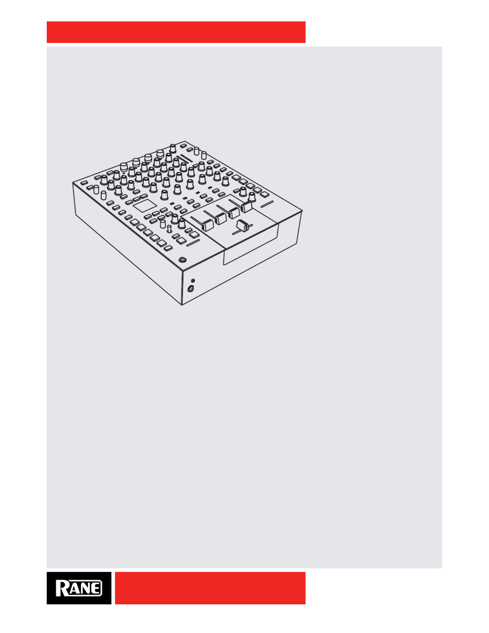
Sixty-Four
Læs nedenfor 📖 manual på dansk for Rane Sixty-Four (48 sider) i kategorien Blandekonsol. Denne guide var nyttig for 14 personer og blev bedømt med 4.5 stjerner i gennemsnit af 2 brugere
Side 1/48
OWNER’S MANUAL
SIXTY-FOUR
RANE
SIXTY-FOUR
MIXER
MANUAL

OWNER’S MANUAL
2
SIXTY-FOUR
ATTENTION: RISQUE DE CHOCS ELECTRIQUE - NE PAS OUVRIR
RISK OF ELECTRIC SHOCK
DO NOT OPEN
CAUTION
To reduce the risk of electrical shock, do not open the unit. No
user serviceable parts inside. Refer servicing to qualied service
personnel.
The symbols shown below are internationally accepted symbols
that warn of potential hazards with electrical products.
This symbol indicates that a dangerous voltage
constituting a risk of electric shock is present
within this unit.
This symbol indicates that there are important
operating and maintenance instructions in the
literature accompanying this unit.
WARNING
Important Safety Instructions
1. Read these instructions.
2. Keep these instructions.
3. Heed all warnings.
4. Follow all instructions.
5. Do not use this apparatus near water.
6. Clean only with a dry cloth.
7. Do not block any ventilation openings. Install in accordance with manufacturer’s instructions.
8. Do not install near any heat sources such as radiators, registers, stoves, or other apparatus (including ampliers) that produce heat.
9. Do not defeat the safety purpose of the polarized or grounding-type plug. A polarized plug has two blades with one wider than the other. A
grounding-type plug has two blades and a third grounding prong. The wide blade or third prong is provided for your safety. If the provided plug
does not t into your outlet, consult an electrician for replacement of the obsolete outlet.
10. Protect the power cord and plug from being walked on or pinched particularly at plugs, convenience receptacles, and the point where it exits
from the apparatus.
11. Only use attachments and accessories specied by Rane.
12. Use only with the cart, stand, tripod, bracket, or table specied by the manufacturer, or sold with the apparatus. When a cart is used, use
caution when moving the cart/apparatus combination to avoid injury from tip-over.
13. Unplug this apparatus during lightning storms or when unused for long periods of time.
14. Refer all servicing to qualied service personnel. Servicing is required when the apparatus has been damaged in any way, such as power supply
cord or plug is damaged, liquid has been spilled or objects have fallen into the apparatus, the apparatus has been exposed to rain or moisture,
does not operate normally, or has been dropped.
15. The plug on the power cord is the AC mains disconnect device and must remain readily operable. To completely disconnect this apparatus from
the AC mains, disconnect the power supply cord plug from the AC receptacle.
16. This apparatus shall be connected to a mains socket outlet with a protective earthing connection.
17. When permanently connected, an all-pole mains switch with a contact separation of at least 3 mm in each pole shall be incorporated in the
electrical installation of the building.
18. If rackmounting, provide adequate ventilation. Equipment may be located above or below this apparatus, but some equipment (like large power
ampliers) may cause an unacceptable amount of hum or may generate too much heat and degrade the performance of this apparatus.
19. This apparatus may be installed in an industry standard equipment rack. Use screws through all mounting holes to provide the best support.
WARNING: To reduce the risk of re or electric shock, do not expose this apparatus to rain or moisture. Apparatus shall not be exposed to dripping
or splashing and no objects lled with liquids, such as vases, shall be placed on the apparatus.
NOTE: This equipment has been tested and found to comply with the limits for a Class B digital device, pursuant to part 15 of the FCC Rules.
These limits are designed to provide reasonable protection against harmful interference in a residential installation. This equipment generates, uses
and can radiate radio frequency energy and, if not installed and used in accordance with the instructions, may cause harmful interference to radio
communications. However, there is no guarantee that interference will not occur in a particular installation. If this equipment does cause harmful
interference to radio or television reception, which can be determined by turning the equipment off and on, the user is encouraged to try to correct
the interference by one or more of the following measures:
• Reorient or relocate the receiving antenna.
• Increase the separation between the equipment and receiver.
• Connect the equipment into an outlet on a circuit different from that to which the receiver is connected.
• Consult the dealer or an experienced radio/TV technician for help.
CAUTION: Changes or modications not expressly approved by Rane Corporation could void the user's authority to operate the equipment.
CAN ICES-3 (B)/NMB-3(B)
WARNING: This product may contain chemicals known to the State of California to cause cancer, or birth defects or other reproductive harm.

OWNER’S MANUAL
3
SIXTY-FOUR
ATTENTION: RISQUE DE CHOCS ELECTRIQUE - NE PAS OUVRIR
RISK OF ELECTRIC SHOCK
DO NOT OPEN
CAUTION
An d’éviter tout risque de choc électrique, ne pas ouvrir l’appareil.
Aucune pièce ne peut être changée par l’utilisateur. Contactez un
SAV qualié pour toute intervention.
Les symboles ci-dessous sont reconnus internationalement comme
prévenant tout risque électrique.
Ce symbole indique que cette unité utilise un voltage
élevé constituant un risque de choc électrique.
Ce symbole indique la présence d’instructions
d’utilisation et de maintenance importantes dans le
document fourni.
ATTENTION
Instructions de Sécurité
1. Lisez ces instructions.
2. Gardez précieusement ces instructions.
3. Respectez les avertissements.
4. Suivez toutes les instructions.
5. Ne pas utiliser près d’une source d’eau.
6. Ne nettoyer qu’avec un chiffon doux.
7. N’obstruer aucune évacuation d’air. Effectuez l’installation en suivant les instructions du fabricant.
8. Ne pas disposer près d’une source de chaleur, c-à-d tout appareil produisant de la chaleur sans exception.
9. Ne pas modier le cordon d’alimentation. Un cordon polarisé possède 2 lames, l’une plus large que l’autre. Un cordon avec tresse de masse
possède 2 lames plus une 3è pour la terre. La lame large ou la tresse de masse assurent votre sécurité. Si le cordon fourni ne correspond pas à
votre prise, contactez votre électricien.
10. Faites en sorte que le cordon ne soit pas piétiné, ni au niveau du l, ni au niveau de ses broches, ni au niveau des connecteurs de vos appareils.
11. N’utilisez que des accessoires recommandés par Rane.
12. N’utilisez que les éléments de transport, stands, pieds ou tables spéciés par le fabricant ou vendu avec l’appareil. Quand vous utlisez une
valise de transport, prenez soin de vous déplacer avec cet équipement avec prudence an d’éviter tout risque de blessure.
13. Débranchez cet appareil pendant un orage ou si vous ne l’utilisez pas pendant un certain temps.
14. Adressez-vous à du personnel qualié pour tout service après vente. Celui-ci est nécessaire dans n’importe quel cas où l’appareil est abimé :
si le cordon ou les ches sont endommagés, si du liquide a été renversé ou si des objets sont tombés sur l’appareil, si celui-ci a été exposé à la
pluie ou l’humidité, s’il ne fonctionne pas correctement ou est tombé.
15. La che du cordon d’alimentation sert à brancher le courant alternatif AC et doit absolument rester accessible. Pour déconnecter totalement
l’appareil du secteur, débranchez le câble d’alimentation de la prise secteur.
16. Cet appareil doit être branché à une prise terre avec protection.
17. Quand il est branché de manière permanente, un disjoncteur tripolaire normalisé doit être incorporé dans l’installation électrique de l’immeuble.
18. En cas de montage en rack, laissez un espace sufsant pour la ventilation. Vous pouvez disposer d’autres appareils au-dessus ou en-dessous
de celui-ci, mais certains (tels que de gros amplicateurs) peuvent provoquer un buzz ou générer trop de chaleur au risque d’endommager votre
appareil et dégrader ses performances.
19. Cet appareil peut-être installé dans une baie standard ou un chassis normalisé pour un montage en rack. Visser chaque trou de chaque oreille
de rack pour une meilleure xation et sécurité.
ATTENTION: an d’éviter tout risque de feu ou de choc électrique, gardez cet appareil éloigné de toute source d’humidité et
d’éclaboussures quelles qu’elles soient. L’appareil doit également être éloigné de tout objet possédant du liquide (boisson en
bouteilles, vases,…).
REMARQUE: Cet équipement a été testé et approuvé conforme aux limites pour un appareil numérique de classe B, conformément au chapitre 15
des règles de la FCC. Ces limites sont établis pour fournir une protection raisonnable contre tout risque d’interférences et peuvent provoquer une
énergie de radiofréquence s'il n'est pas installé et utilisé conformément aux instructions, peut également provoquer des interférences aux niveaux
des équipements de communication. Cependant, il n'existe aucune garantie que de telles interférences ne se produiront pas dans une installation
particulière. Si cet équipement provoque des interférences en réception radio ou télévision, ceci peut être detecté en mettant l'équipement sous/
hors tension, l'utilisateur est encouragé à essayer de corriger cette interférence par une ou plusieurs des mesures suivantes:
• Réorienter ou déplacer l'antenne de réception.
• Augmenter la distance entre l'équipement et le récepteur.
• Connecter l'équipement à une sortie sur un circuit différent de celui sur lequel le récepteur est branché.
• Consulter un revendeur ou un technicien radio / TV expérimenté.
ATTENTION: Les changements ou modications non expressément approuvés par Rane Corporation peuvent annuler l'autorité de l'utilisateur à
manipuler cet équipement et rendre ainsi nulles toutes les conditions de garantie.
CAN ICES-3 (B)/NMB-3(B)
Cartons et papier à recycler.

OWNER’S MANUAL
4
SIXTY-FOUR
Copyright Notices
©2013 Rane Corporation. All rights reserved. Serato DJ and Scratch Live are trademarks of Serato.
Trademarked in the United States and other countries. This software is based in part on the work of the
Independent JPEG Group, and uses libpng code, copyright © 2000-2002 Glenn Randers-Pehrson. The
Serato NoiseMap ™ Control Tone, the audio pressed on Serato Control vinyl and Control CDs, is copyright
©2004-2013 Serato. The Control Vinyl and Control CDs are licensed for personal use only. The creation of
personal backups of the Control CD is allowed, however duplicating Control CDs for commercial benet is
strictly prohibited. For avoidance of doubt the duplication or creation of Control vinyl for any use is strictly
prohibited. Please respect our copyright. Windows® is a registered trademark of Microsoft Corporation in
the United States and other countries. Apple, Mac, Macintosh, iTunes, Safari, QuickTime, GarageBand,
and OS X are registered trademarks of Apple Inc., registered in the United States and other countries.
Check List
These items are included in the box:
• Sixty-Four Mixer.
• Serato DJ software and drivers install disc.
• 4 (four) control CDs.
• 4 (four) control records.
• 2 USB cables.
• IEC C5 line cord.
• Serato DJ Software Manual.
• This Sixty-Four Mixer Manual.
Wear Parts
The Sixty-Four Mixer contains no wear parts. The control vinyl records and CDs are wear parts as
described in "Limited Warranties" on page 46.

OWNER’S MANUAL
5
SIXTY-FOUR
Contents
2 Important Safety Instructions
6 Quick Start: Software
6 Serato DJ Software Installation for Mac OSX
6 Serato DJ Software Installation for Windows
6 Other DJ and DAW Programs
7 Quick Start: Hardware
10 Sixty-Four Overview
11 Sixty-Four Connections
12 Deck Input Channels
13 Headphone Cueing
14 Software Controls
14 Control Assignment
14 Library Scroll and Load
14 Auto Loop Controls
15 Slip
15 Sync
15 MIDI Triggers 1-8
15 MIDI Layers
16 Microphone Inputs
16 Main Mix
17 FlexFX Loop
18 Effects Engine
18 FILTER Effect
18 FLANGER Effect
18 PHASER Effect
19 ECHO Effect
19 ROBOT Effect
19 REVERB Effect
19 Effects Display and BPM Source
20 Effects Synchronization
21 Effects Parameter Table
22 USB Audio
23 USB Playback Channels Assignment
23 USB Record Channel Assignment
24 Shift Options
24 Ext. Insert Options Menu
24 Filter Effect Options Menu
24 Flanger Effect Options Menu
24 Echo Effect Options Menu
25 Deck 1-4 Input Channel Options Menu
25 Main Mix Options Menu
25 Mixer Shift Functions
25 MIDI Start/Stop
25 Nudge
25 BPM Adjust
26 DJ Changeover
27 Rane Drivers
27 ASIO (Windows)
27 Core Audio (Macintosh)
27 Preferences Screen
28 Deck Inputs 1-4 Screen
28 Effects Screen
29 MIDI Conguration Screen
29 Factory Defaults
30 MIDI Mapping
33 MIDI Implementation
40 Fader Maintenance
42 Rack Mounting Accessory
43 Technical Specifications
45 Declaration of Conformity
46 Limited Warranties

OWNER’S MANUAL
6
SIXTY-FOUR
Quick Start: Software
Before using your mixer, at least read this short section for the basics. Read the complete manual to get
the best investment from your new Sixty-Four. This section will help get you started with one computer.
Serato DJ Software Installation for Mac OSX
Before installing, we recommend you check for a
newer version of Serato DJ at serato.com/downloads
and install the latest Serato DJ version if it is newer
than the version on the CD-ROM that comes with your mixer.
1. Insert the Serato DJ Installer CD-ROM that came with your unit,
-or-
browse using Finder to the location where the Serato DJ download was saved.
2. Double click the Serato DJ .dmg installer le.
3. The software EULA screen will appear - read the License Agreement, then click Agree.
4. The disk image mounts and opens the actions folder, once this is nished you can unmount the disk
image and launch Serato DJ.
5. Drag the Serato DJ application icon to the Applications folder alias.
6. You may then need to enter your User Password to authenticate.
7. Serato DJ will now copy to the Applications folder, once this is nished you can unmount the disk image
and launch Serato DJ.
Serato DJ Software Installation for Windows
Before installing, we recommend you download and install the latest Serato DJ version from serato.com if
it is newer than the version on the CD-ROM that comes with your mixer.
1. Insert the Serato DJ Installer CD-ROM that came with your unit,
-or-
browse using Windows Explorer to the location where the Serato DJ download installer was saved.
2. Double click the Serato DJ .exe installer le.
3. Accept the Security Warning and click “Run”.
4. The installer introduction screen will appear, click Next.
5. Read the License Agreement, then tick “I agree to the license terms and conditions,” then click Install.
6. If a User Account Control window appears, click Yes.
7. Serato DJ will now perform a standard installation.
8. The installation is now complete. You can now click Close.
NOTE: A shortcut will be also be created on desktop.
When you first connect your Sixty-Four Mixer via USB, you may see a request to install drivers.
Accept the request and allow the driver installation to proceed. After drivers are installed, a Sixty-Four
control panel will be available, and your software will recognize the Sixty-Four.
After Serato DJ is installed, you will be prompted to "Install Driver" in the Online Panel if you connect a
new compatible device that has not already had its driver installed.
Other DJ and DAW Programs
Rane drivers come with the Serato DJ installer to use other software. See "Rane Drivers" on page 27.
Check Firmware When Installing a Newer Serato DJ Version
The mixer's rmware may need updating when Serato DJ is updated. See "Rane Drivers" on page 27.
OWNER’S MANUAL
7
SIXTY-FOUR
MAIN OUT
SEND
PHONO
GROUNDS
MIC 1
MIC 2
SESSION
AUX
ANALOG INPUTS
MIC INPUTS
LEFT (MONO)
100-240V 50/60 Hz 15 WATTS
LEFT
RIGHT
RANE CORPORATION
RIGHT
RETURN
SESSION
FLEXFX LOOP
LEFT
RIGHT
USB A
USB B
BOOTH OUT
LEFT
RIGH
IN
IN
OUT
R
L
1
3
R
L
4
IN
OUT
S/PDIF
2
PH - CD
PH - CD
OFF - +48
PH - CD
PH - CD
R
L
MIC - LINE
SIXTY-FOUR
USB
TURNTABLE OUTTURNTABLE OUT
POWERED POWERED
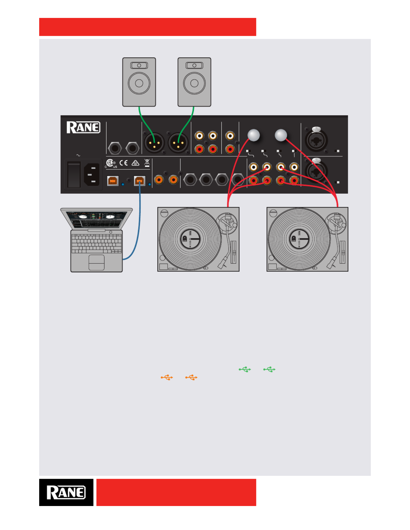
Quick Start: Hardware
This section will help you get your decks connected and music playing. Turn the power off while
connecting your decks and ampliers.
Analog Inputs
1. Serato DJ has four virtual Decks 1-4. On the mixer, Decks 1 and 2 are typically used as the primary
Decks, and Decks 3 and 4 as secondary decks. For DVS operation, connect the corresponding analog
inputs to the appropriate Decks and set the rear panel PH/CD switches as required.
2. For DVS playback, set the selector switches to the appropriate USB playback channel for each Deck.
For example if connected to USB Port A, set input selectors to , etc. If connected to 1A 2A
USB Port B, set input selectors to , etc. Note that audio and MIDI for each Deck will be 1B 2B
routed to the correct USB Port.
3. For direct analog playback, set source selectors to PH/CD. THRU will be indicated on each software
virtual deck set to an analog input source.
OWNER’S MANUAL
8
SIXTY-FOUR
3B 2B 4B1B3A 2A 4A1A
PH/CD 3
Port A
= green
Alternates strip control
assign to Deck 3 or 1.
Assign to
Deck 2 or 4.
Port A = green
Port B = orange
Port B
= orange AUX
CONTROL
PH/CD 2 AUX
CONTROL
PH/CD 4 AUX
CONTROL
PH/CD 1 AUX
CONTROL
DECK 3 / 1
3124
TAB
DECK 2 / 4
TAB
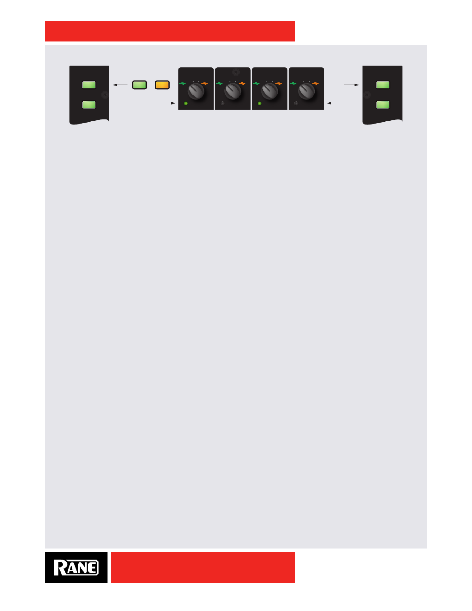
For control of opposing decks, the center channels of the Sixty-Four are wired to Decks 1 and 2, and the
outside channels are wired to 3 and 4. This places pairs of decks centered over the crossfader.
Press the Deck 3 / 1 button to assign the left-hand control strip to Deck 3 or Deck 1. Similarly, press the
Deck 2 / 4 button to assign the right-hand control strip to Deck 2 or Deck 4. The Control LED under each
source selector shows the currently assigned Deck. The source selectors route Audio and MIDI to and
from USB Port A or Port B.
Analog Outputs
• Main Out is on a pair of balanced XLR jacks with pin 2 “hot” per AES standards.
• Booth Out is on a pair of balanced ¼˝ TRS (tip-ring-sleeve) jacks.
• Session Out is available on a pair of unbalanced RCA jacks.
• Headphones output is available on both ¼˝ TRS and 3.5 mm jacks.
The Main, Booth and Session outputs come from the same “Main Mix” signal. Main, Booth and Session
outputs each have their own Level control. Because all signals are identical, you may use any of these
outputs as the “Main” output if a different cable is required for system connection.
Rane recommends balanced wiring for the strongest signal and rejection of hum and noise. If your
cable to the destination is less than 10 feet (3 meters), you can often get away with an unbalanced cable.
See the RaneNote “Sound System Interconnection” at rane.com for cable wiring recommendations.
Calibrating Serato DJ for Control Vinyl or CD
Since Serato DJ is controlled by an analog signal, there is no guarantee of what state that signal will be in
by the time the software gets to interpret it. Therefore, Serato DJ needs to be able to handle a wide range
of signals, and be congurable to use them optimally. Calibrating is just conguring the software to your
situation. Calibration is equally important for both vinyl and CD users of Serato DJ.
There are two parts to the Serato DJ Control Vinyl: The directional tone, and the NoiseMap™. Listening
to the control vinyl, the directional tone is the 1 kHz tone. The noise map sounds like random noise over
the top of the tone. The directional tone provides the current speed and direction of the record, while the
noise map tells the software precisely where on the record the needle is currently.
The Noise Sensitivity slider lets you adjust the noise threshold. A threshold is a lower limit, below which
a process will not occur. In the case of Serato DJ, the noise threshold is the limit below which the input
signal will not be interpreted as control signal; in other words if it’s below the threshold, it is considered
noise and ignored.
This setting is necessary because a stylus is very sensitive, and will inevitably pick up noise from the
environment as well as the signal on the record, especially in the noisy environment of a live show.

OWNER’S MANUAL
9
SIXTY-FOUR
How To Calibrate Serato DJ
With music playing in the background through your system or booth output, put your needle on the record
with the turntable stopped. If you are using CD players, the same rules apply. Have the CD deck paused
or stopped while calibrating.
Click and hold the estimate button until the slider stops moving. Moving the Noise Sensitivity slider
to the left will make Serato DJ more sensitive to slow record movement, but also more sensitive to
background noise.
Repeat the process for each deck.
Things to remember:
• Your needle must be on the record.
• Your turntable (or CD player) must be stationary.
• The background music playing must be at a similar level to
which you will play your set at.
• Calibrate Serato DJ every time you play.
TIP: If the slider jumps to the far right, then you have a problem
with noise in your turntables/CD players/mixer. Check all your
connections and make sure your equipment is well earthed.
In some situations you will not be able to improve the signal
quality, and you will have to play on regardless. In this situation,
stick to rel mode.
The Scopes
The scopes on the setup screen in Serato DJ display the input signal as a phase diagram. The key factors
to look at on the scope display are crisp clean lines, round shape, and the tracking percentage in the
lower right corner.
Start both turntables or CD players. You will see green rings appear in the scope view, as shown above.
For optimal performance the inner ring should be as close to circular as possible. Use the scope
zoom slider to zoom in or out as necessary. Use the scope L/R balance and P/A balance controls to
adjust the shape of the inner ring. The number in the top left corner of the scope view gives the current
absolute position within the control record or CD. The number in the top right corner is the current speed
in RPM. In the bottom left is the current threshold setting, and the number in the bottom right shows
the percentage of readable signal – this number should be close to 85% when your system is calibrated
properly.
Calibration Troubleshooting
After calibration, the number in the upper right corner of the scope view should say 0.0 while the needle is
on the record and the turntable is stopped.
If that number is uctuating then manually move the estimate slider to the right until that number is
stable at 0.0. If you’ve moved the slider all the way to -24 and its still uctuating then you have a grounding
or interference problem somewhere in the chain.
If so, the rst thing to check is that the grounding wire coming from your turntable is connected to your
mixer’s grounding posts.
Next, make sure that the hardware isn’t sitting next to a power source such as a power strip or power
box and that the RCA cables connected to the hardware aren’t laying across other power conducting
cables.
If you are still experiencing issues, you might have to adjust the placement of your setup. For example,
make sure bass bins aren’t directly under the turntables.
More help is in the Troublshooting section of the Serato DJ software manual.

OWNER’S MANUAL
10
SIXTY-FOUR
Sixty-Four Overview
Software controls are built-in for one or two computers
• Includes Serato DJ software.
Includes Rane ASIO and Core Audio Drivers for Serato DJ and other audio programs.•
• Advanced MIDI and audio routing: route any deck to either USB Port, and MIDI follows the audio.
• Control Library, Cues, Loops and Samples on two computers.
30 controls with 157 unique mappings for software.•
• Each of the two USB ports supports six stereo record and ve stereo playback channels.
• USB record channels support:
Vinyl control signal for four Virtual Decks, record any one of the four Decks post-fader.• or
Record the Main Mix, Mic 1 or Mic 2.•
FlexFX USB Insert Send to each computer.•
• USB playback channels support:
• Playback for four Virtual Decks.
FlexFX USB Insert Return from each computer.•
• Great-sounding 32-bit oating-point audio sampled at 48 kHz.
Deck input channel controls
• Pre-fader Level, 3-band isolator EQ, low-pass / high-pass sweep Filter with resonance adjustment.
• Crossfader, FlexFX and headphone Cue assigns.
• Proprietary magnetic crossfader with a contour control.
• Contour control for the channel faders.
Two Mic inputs
• Mic 1 includes a Phantom power switch.
• Mic 2 includes a Mic / Line level switch.
• Controls: On / Off, Level, Pan, Tone and
FlexFX assign for each Mic.
• Unused Mic controls easily map to MIDI.
Advanced post-fader FlexFX
• Internal Effects engine with:
Filter, Flanger, Phaser, Echo, Robot and •
Reverb.
MIDI beat clock track and generate.•
Sync BPM with Serato DJ, MIDI beat •
clock or manual Tap button.
• USB Insert loop for post-fader software
effects for each of the two ports.
• External analog insert loop for outboard
effect units.
Main Mix section
• Balanced XLR Main Mix and
1/4" TRS Booth outputs.
• RCA analog and S/PDIF Session In / Out.
Headphone monitor with split cueing.
DECK 3 DECK 1 DECK 2 DECK 4
Deck Input Channels Main
Mix
Headphone Cue
Software
Controls
Software
Controls
Mic Inputs
FlexFX

OWNER’S MANUAL
11
SIXTY-FOUR
Sixty-Four Connections
Power Supply
The Sixty-Four Mixer features an internal universal switching power supply that operates on any AC
mains 100 to 240 VAC, 50 or 60 Hz (most places in the world). All that is required when traveling is the
appropriate IEC line cord, available from a local electronics store. The universal supply is a major plus for
the traveling DJ. Though this mixer has turn on/off muting, it’s smart to leave the power unplugged until
everything else is connected.
Mixer Inputs
• One stereo Phono / CD input is provided for each of the four Decks on a pair of RCA jacks. Each may
be set for PH or CD using rear panel slide switches. Set unused inputs to CD. Connect your turntable
ground wires to the ground posts provided on the rear panel when using PH inputs.
• There is one stereo unbalanced Aux input on RCA jacks. This input may be selected as a source by any
of the four Deck channels.
• One stereo Session Input is available on a pair of RCA jacks. This input may be used for connecting two
mixers together or as a general purpose auxiliary input to the mixer. There is also an S/PDIF Session
Input that may be used in combination with the S/PDIF Session Output on another mixer to digitally link
mixers without converting to analog.
• There are two balanced microphone inputs on combination TRS / XLR jacks. Mic 1 has phantom power
available. Mic 2 may be set for Mic or Line level input.
• Stereo FlexFX Loop Return input is on a pair of unbalanced 1/4" TS jacks. These inputs are
automatically congured for mono when only one cable is connected to the left or right Return input.
The FlexFX Return input is normally used in combination with the FlexFX Send output to connect an
outboard analog effects processor.
Mixer Outputs
• Main Out is on a pair of balanced XLR jacks.
• Booth Out is on a pair of balanced 1/4" TRS jacks.
• Session Out is available on a pair of unbalanced RCA jacks, and digitally via S/PDIF on an RCA jack.
• FlexFX Loop Send output is available on a pair of unbalanced 1/4" TS jacks. For a mono FlexFX Send,
use the Left output. The FlexFX Send output is normally used in combination with the FlexFX Loop
Return input to connect outboard analog effects.
Two USB Ports
The Sixty-Four allows simultaneous connection of two computers. Each port is completely independent.
Rane's ASIO (PC) and Core Audio (Mac) drivers connect to most audio software. It is possible to
run Serato DJ on one computer while running third-party software on the other, Mac or PC, in any
combination. Either port connects to a single computer. See "Software Controls" on page 14.
MAIN OUT
SEND
PHONO
GROUNDS
MIC 1
MIC 2
SESSION
AUX
ANALOG INPUTS
MIC INPUTS
LEFT (MONO)
100-240V 50/60 Hz 15 WAT TS
LEFT
RIGHT
RANE CORPORATION
RIGHT
RETURN
SESSION
FLEXFX LOOP
LEFT
RIGHT
USB A
USB B
BOOTH OUT
LEFT
RIGHT
IN
IN
OUT
R
L
1
3
R
L
4
IN
OUT
S/PDIF
2
PH - CD
PH - CD
OFF - +48
PH - CD
PH - CD
R
L
MIC - LIN
SIXTY-FOUR
OWNER’S MANUAL
12
SIXTY-FOUR
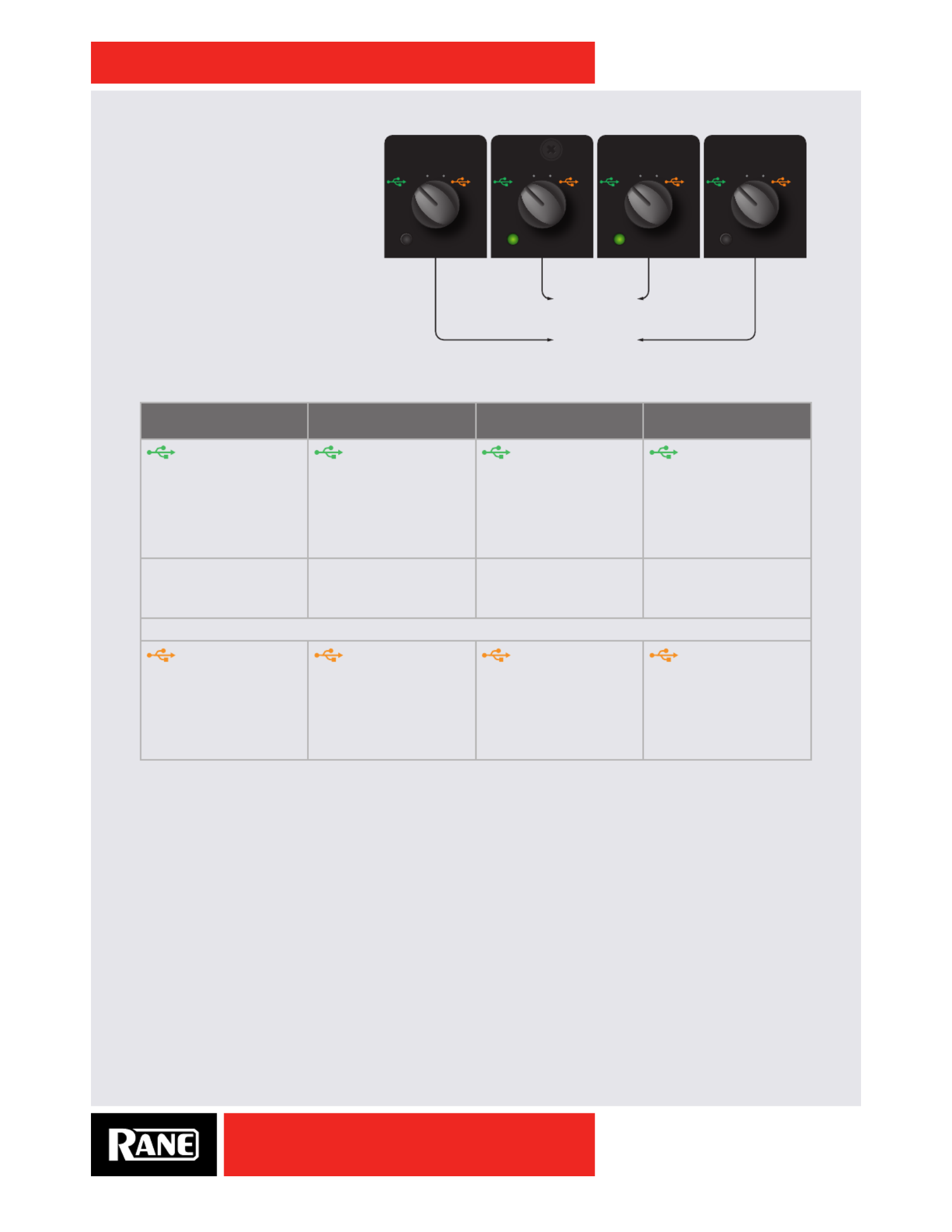
Deck Input Channels
Source Selectors
For control of opposing decks, the
center channels of the Sixty-Four
are wired to Decks 1 and 2, and
the outside channels are wired to
3 and 4. This places pairs of decks
centered over the crossfader. For a
shared set example, the rst DJ can
take Decks 1&2, and the second DJ
can take Decks 3&4.
The source selectors choose the active USB port, USB audio slot or analog input for each input channel.
Deck 3 Source
Selections
Deck 1 Source
Selections
Deck 2 Source
Selections
Deck 4 Source
Selections
Port A playback
for Deck 3
• USB audio slots 1-2.
• Routes audio and
MIDI for Deck 3 only
to/from USB Port A.
Port A playback
for Deck 1
• USB audio slots 3-4.
• Routes audio and
MIDI for Deck 1 only
to/from USB Port A.
Port A playback
for Deck 2
• USB audio slots 5-6.
• Routes audio and
MIDI for Deck 2 only
to/from USB Port A.
Port A playback
for Deck 4
• USB audio slots 7-8.
• Routes audio and
MIDI for Deck 4 only
to/from USB Port A.
• Phono / CD 3
• PH-CD switch on the
rear panel.
• Phono / CD 1
• PH-CD switch on the
rear panel.
• Phono / CD 2
• PH-CD switch on the
rear panel.
• Phono / CD 4
• PH-CD switch on the
rear panel.
• Aux Input (common to all selectors).
Port B playback
for Deck 3
• USB audio slots 1-2.
• Routes audio and
MIDI for Deck 3 only
to/from USB Port B.
Port B playback
for Deck 1
• USB audio slots 3-4.
• Routes audio and
MIDI for Deck 1 only
to/from USB Port B.
Port B playback
for Deck 2
• USB audio slots 5-6.
• Routes audio and
MIDI for Deck 2 only
to/from USB Port B.
Port B playback
for Deck 4
• USB audio slots 7-8.
• Routes audio and
MIDI for Deck 4 only
to/from USB Port B.
For details on sharing the Sixty-Four with a second computer, see "DJ Changeover" on page 26.
3B 2B 4B1B3A 2A 4A1A
PH/CD 3 AUX PH/CD 2 AUX PH/CD 4 AUXPH/CD 1 AUX
3 1 2 4
mix pair 1-2
mix pair 3-4
CONTROL CONTROL CONTROLCONTROL

OWNER’S MANUAL
13
SIXTY-FOUR
Deck Source Selection is followed by:
• Level (gain trim)
Off to +12 dB with unity gain at 12 o’clock.•
• Q-peak meter with peak hold
Adjust the channel Level to get the signal into the •
yellow during peaks, and to prevent overload.
• 3-band isolator EQ
Off to +6 dB with unity gain at 12 o’clock.•
• High-pass / low-pass Filter
No effect at the center (at response).•
Low-pass lter cutoff moves from 20 kHz toward •
20Hz as the knob is turned CCW.
High-pass lter cutoff moves from 20 Hz toward •
20kHz as the knob is turned CW.
• Crossfader assign
• Routes the Deck to Crossfader A-side, Post-
crossfader or B-side.
• FlexFX assign
Takes a Deck out of the Main Mix and sends it to the •
FlexFX Loop. See "FlexFX Loop" on page 17.
• Cue select
• Assigns a Deck to the headphone monitor.
• Channel Fader
• All four channel faders share the Fader Contour
control, adjustable from a fast cut (left) to a smooth
fade (right).
• Crossfader
• The magnetic crossfader is easily cleaned or eld-
replaced. See "Fader Maintenance" on page 40.
Use the Crossfader assign switches to send each •
Deck to the A-side, B-side or Post-crossfader.
Adjust from a fast cut (left) to a smooth fade (right) •
with the Crossfader Contour control.
Headphone Cueing
• The Headphone monitor provides stereo or mono split cue operation.
When set for stereo operation (dim), the Pan control pans between stereo Cue and •
stereo Main Mix.
When set for Split Cue operation (bright), the Pan control pans between Mono Cue in •
the left ear and mono Main Mix in the right ear.
• Individual Cue buttons are provided for Deck 1, Deck 2, Deck 3, Deck 4 and FlexFX.
• Cue buttons are solo, meaning when a Cue is selected all other Cues are turned off. If
you wish to listen to more than one Cue at a time, press both buttons at the same time.
• The Phones control sets the level to the headphone jacks.
• Headphones output is available on two 1/4" jacks, one on the front and one on the top.
An additional 3.5 mm jack is located on the front. All share the same signal.

OWNER’S MANUAL
14
SIXTY-FOUR
Software Controls
Control Assignment
Press the Deck 3 / 1 button to assign the left-hand controls to Deck 3 or
Deck 1. Similarly, press the Deck 2 / 4 button to assign the right-hand
controls to Deck 2 or Deck 4. The Control LED under each source selector
shows the currently assigned Deck. The source selectors route Audio and
MIDI to and from USB Port A or Port B. See "Source Selectors" on page
12. MIDI button backlighting is independently maintained for each USB
port and each deck. This way audio and MIDI assigned to one USB port do
not interfere with audio and MIDI assignments on the other port.
Library Scroll and Load
The Tab button sets the cursor in the Serato DJ Crates column. Rotate the
Scroll encoder to highlight the desired Crate then press the encoder down
to select it. This crate selection puts the cursor in the song column. Turn
the Scroll encoder to select a song and press the encoder down to load it.
Library controls have xed functions and are not affected by the selected
MIDI Layer (see Layers below).
Auto Loop Controls
Tracks need BPM information added to their id3 tags before the auto loops
will work (see Analyzing Files in the Serato DJ Manual.) Creating manual
loops does not require BPM information.
Turning the Loop encoder changes the length of the current loop in
Serato DJ, and can be adjusted while an auto loop is already looping.
Clicking down on the Loop Encoder cuts the loop length in half.
The Loop button turns on the selected auto loop (if the track is properly
tagged with a correct BPM). If there is already an active loop (manual or
auto), the Loop buttons turn off that loop. To adjust an existing loop length, it
must be active and tagged with a proper BPM.
Press and hold the Roll button to turn ON a Loop Roll and release it to
turn the Loop Roll OFF. Loop Roll is different because when the loop is
turned off, the playback position is returned to the position where it would be
if it had not entered the loop (much like censor). Short loop lengths create stutter effects.
You can save an active loop by holding the Shift button down and pressing the Loop Encoder. The loop
is then saved in the next available loop slot.
The rst four saved loops can be triggered in second BANK of Layer 1 (Cues 4-8.)
You can also trigger all eight saved loops in Layer 4. See "MIDI Triggers 1-8" on page 15.
Pressing a green trigger button will jump to the beginning of the Loop and turn it on (Reloop.)
To toggle a Loop off and on, regardless of the play position, hold the Shift button and the
corresponding trigger button. Toggling ON/OFF a loop with these controls will not jump to the beginning
of the selected loop.
For all Loop functions and sofware operation, see Looping in the Serato DJ Manual.
3B 2B 4B1B3A 2A 4A1A
LAYER 1
(CUE / LOOP)
(SAMPLES)
SYNC OFF
(CUE / LOOP)
(SAMPLES)
SYNC OFF
LAYER 2
LAYER 3
LAYER 4
LAYER 1
LAYER 2
LAYER 3
LAYER 4
SCROLL / LOAD
LOOP
SYNC
LAYER
SCROLL / LOAD
LOOP
ROLL
SLIP
LOOP
SYNC
LOOP
ROLL
SLIP
PH/CD 3
Port A
= green
Alternates strip control
assign to Deck 3 or 1.
Assign to
Deck 2 or 4.
Port A = green
Port B = orange
Port B
= orange AUX
CONTROL
PH/CD 2 AUX
CONTROL
PH/CD 4 AUX
CONTROL
PH/CD 1 AUX
CONTROL
BANK
1 5
2 6
3 7
4 8
LAYER
5 1
6 2
7 3
8 4
DECK 3 / 1
3124
TAB
DECK 2 / 4
TAB
BANK
OWNER’S MANUAL
16
SIXTY-FOUR
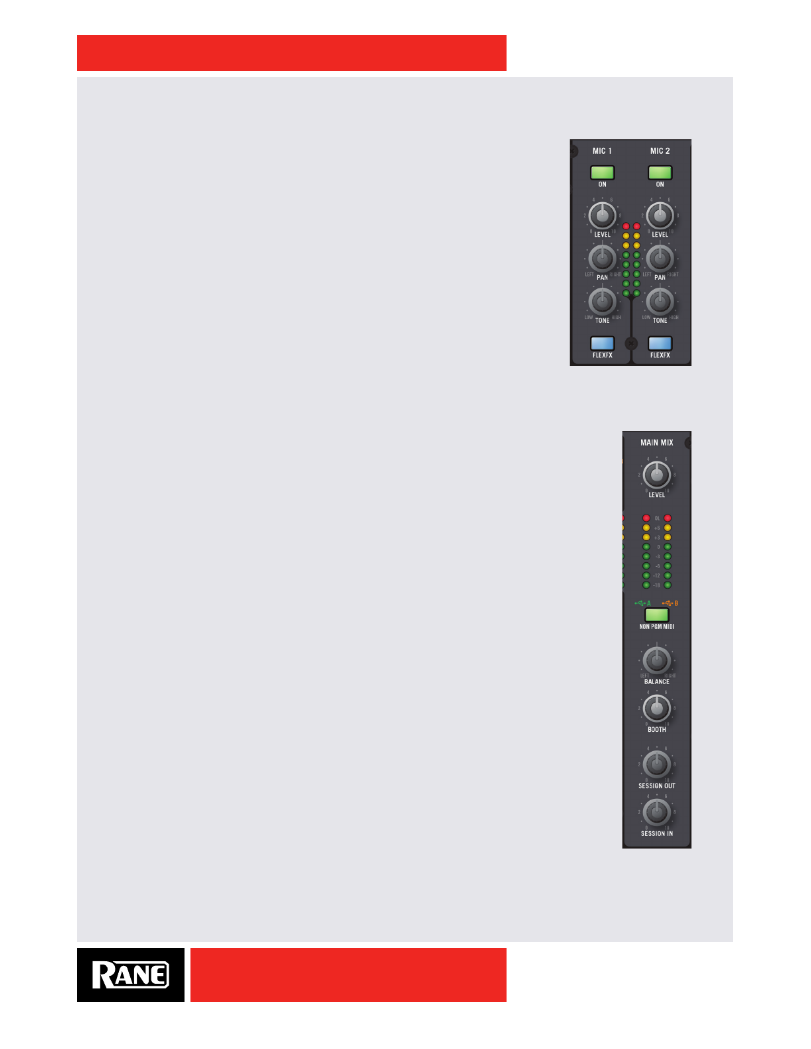
Microphone Inputs
There are two fully independent mic inputs. Each has these controls:
• On / Off switch.
• Level Control.
• Left / Right Pan.
• One-knob spectral tilt Tone control:
Increasing highs reduces lows by the same amount.•
Decreasing highs increases lows by the same amount.•
• FlexFX Assign:
Takes the signal out of the Main Mix and sends it to the FlexFX Loop.•
• Mic 1 can provide 48 volt phantom power for a condenser mic:
The 48V phantom power on/off switch is on the rear panel.•
• Mic 2 allows a Mic level or Line level input for a wireless mic:
The Mic / Line switch is on the rear panel.•
• Unused Mic inputs can be MIDI controls. See "Mic Bypass Mode" on page
30.
Main Mix
• These signals combine to make the Main Mix signal:
Deck 1, Deck 2, Deck 3, Deck 4.•
Mic 1 and Mic 2.•
• Session Input.
• FlexFX Mix.
• The Main Mix has these outputs:
• Main:
• Balanced XLR jacks;
Maximum output 8 volts rms.•
• Booth:
• Balanced 1/4" TRS jacks;
Maximum output 8 volts rms.•
• Session:
• Unbalanced RCA jacks;
Maximum output 4 volts rms.•
S/PDIF digital on one RCA jack.•
• Common to all Main Mix outputs:
Stereo or Mono (default is stereo). See "Main Mix Options Menu" on page 25.•
• Left / Right Balance control.
Stereo Q-peak meter with peak hold;•
If the red overload LED is off, the mixer will not clip at any output level setting.•
• Main, Booth and Session outputs have independent Level controls; range is off to 0 dB.
Cabling Note: When using unbalanced 1/4" TS cables from the Booth Outputs or RCA
cables from the analog Session outputs, keep cables short, less than 3 meters (10 feet) to
avoid hum and interference. Balanced 1/4" TRS or XLR cables are the best choice, allowing
greater distance runs without problems.

OWNER’S MANUAL
17
SIXTY-FOUR
FlexFX Loop
The FlexFX loop is a submix that may include any combination of the four Deck
Inputs, Mic 1 and Mic 2. This allows you to create a unique submix, add internal
or external effects to the submix, and record or rehearse the submix.
• The FlexFX Loop consists of these elements in order of processing:
Internal Effects Engine (see "Effects Engine" on page 18•).
• External Analog Insert Loop
Signal is always present at the analog FlexFX Loop Send.•
Press Ext. Insert for input from the 1/4" FlexFX Loop Return jacks.•
Adjustable Sensitivity (see "Ext. Insert Options Menu" on page 24•).
• USB Inserts
Signal is always sent to the USB A and USB B sends.•
Press A Insert to return through USB Port A.•
Press B Insert to return through USB Port B.•
Only one USB Insert return can be active at any time, choose A or B.•
Note: External and USB Inserts are selected individually and available with or
without an internal effect.
• FlexFX Cue monitor “listens” to the affected signal before it is introduced to the
Main Mix through the Level control and the On switch.
• The LEVEL control sets the level of the FlexFX signal in the Main Mix.
• Use when mixing a unique submix.
Use when the level of an effected signal needs adjustment.•
• FlexFX On switch
When off, this bypasses the internal effects, 1/4" analog insert and the USB inserts. What you hear in •
the Main Mix is a dry version of any signal assigned to the FlexFX Loop.
When On, the signal is processed by any selected internal effect, Ext. Insert or USB insert.•
This switch is an on/off switch for the entire loop.•
This switch is not an on/off switch for the internal effects engine. These effects are turned on and •
off individually with the blue effect select buttons.
If the FlexFX Level is turned up and the FlexFX loop is off (bypassed), there is no change heard in the Main
Mix when a channel is assigned to FlexFX. In this instance, it is possible to add internal or external effects
to the signal and Cue the effected signal in the headphones before turning the FlexFX loop ON. It is also
possible to have the FlexFX Level turned down, FlexFX loop On or off, create a submix, add effects (or
not) and Cue or rehearse the mix before bringing it into the Main Mix with the Level control.
The FlexFX submix may be recorded separately via the USB send (slots 9-10) or the 1/4" analog send.
FLEXFXDECK 3
FLEXFXDECK 1
FLEXFXDECK 2
FLEXFXDECK 4
FLEXFXMIC 1
FLEXFXMIC 2
MAXMIN
DEPTH
FILTER
EXT. INSERT
SEND
BEAT
TIME
TAP
PHASERFLANGER
ROBOTECHO REVERB
ON
FLEXFX ON
BYPASS
ON
RETURN
SEN
Effects
Engine
LEF
RIGH
RETUR
LEF
RIGH
SEND
A RETURN
SEN
RETUR
A
Main
Mix
B RETURN
A
B
B
INSERT
Cue
Bus
CUE
MA
MIN
FLEXFX
LEVEL
FLANGER -Fb
BPM:120 * 4:1
2000 ms

OWNER’S MANUAL
18
SIXTY-FOUR
Effects Engine
The internal effects engine is located in the FlexFX Loop. This allows any
combination of Deck 1, Deck 2, Deck 3, Deck 4, Mic 1 and Mic 2 to be assigned
to an effect. The FlexFX Loop supports recording, cueing and Main Mix level
control of assigned channels. There are six built-in effects:
• • Filter Flanger • Phaser • • • Hold Echo Robot Reverb.
Effects share these general behaviors:
• The effect time is saved for each effect.
• Changing BPM for one effect changes the BPM for all effects.
• Tapping the BPM requires at least two taps.
• Changing the Beat multiplier results in an immediate change in effect time.
• Changing the effect time adjusts the multiplier for other effects so that the new
multiplier is as close as possible to the saved effect time.
Typical workow for assigning a deck to an effect is to assign the deck to the
FlexFx Loop, select the desired effect and then turn the effect ON. Note that LFO
effects are synchronized when the FlexFx button is turned ON to ensure that they
start on-beat as expected.
FILTER Effect
The Filter Effect has a swept LFO synchronized to a selected BPM that sweeps
the frequency of the selected lter type. There are four lter options:
• High-pass lter with high-frequency sync.
• High-pass lter with low-frequency sync.
• Low-pass lter with high-frequency sync.
• Low-pass lter with low-frequency sync.
To sync to the BPM at the high point of the sweep, choose high-frequency sync.To sync to the BPM at the
low point of the sweep, choose low-frequency sync. The type of lter is selected in the menu on the mixer
in the "Filter Effect Options Menu" on page 24, or in the "Effects Screen" on page 28. Operation of
controls for the lter is dened in the "Effects Parameter Table" on page 21.
FLANGER Effect
Flanging is an audio effect produced by mixing two identical signals together, with one signal delayed
by a small and gradually changing period, usually smaller than 20 milliseconds. This produces a swept
comb lter effect. Varying the time delay causes these to sweep up and down the frequency spectrum.
Part of the output signal is fed back to the input producing a resonance effect which further enhances the
intensity of the peaks and troughs. The Flanger has two possible modes of operation:
• Positive feedback.
• Negative feedback.
The type of feedback is selected in the menu on the mixer in the "Flanger Effect Options Menu" on page
24, or in the "Effects Screen" on page 28. Operation of controls for the Flanger is dened in the
"Effects Parameter Table" on page 21.
PHASER Effect
The Phaser effect is created by splitting an audio signal into two paths. One path treats the signal with
one or more all-pass lters. When signals from the two paths are mixed, the frequencies that are out
of phase cancel out, creating the phaser's characteristic notches. An LFO (low frequency oscillator)
modulates the frequency of the all-pass lters. Operation of controls for the Phaser is dened in the
"Effects Parameter Table" on page 21.

OWNER’S MANUAL
19
SIXTY-FOUR
ECHO Effect
Echo is an audio effect which records an input signal and then plays it back after a period of time. The
delayed signal may be played back multiple times to create the sound of a repeating, decaying echo. The
amount of recirculation determines the echo decay rate. There are four available Echo options:
• Echo with no feedback lter and adjustable recirculation 0 to 70%.
• Hold Echo with no feedback lter and adjustable recirculation of 0% to 100%.
• Low-Cut Echo with adjustable feedback lter and adjustable recirculation 0 to 70%.
• Low-Cut Hold Echo with adjustable feedback lter and adjustable recirculation of 0% to 100%.
The two feedback-lter types help reduce a “muddy” sound that can result when using a lot of
recirculation. The type of Echo is selected in the menu on the mixer in the "Echo Effect Options Menu" on
page 24, or in the "Effects Screen" on page 28. Operation of controls for the Echo is dened in the
"Effects Parameter Table" on page 21.
ROBOT Effect
The Robot effect is a pitch-shift type that shifts pitch by an amount indicated on the display bar-graph.
The range is -100% (minus one octave) to +100% (plus one octave). Operation of controls for the Robot is
dened in the "Effects Parameter Table" on page 21.
REVERB Effect
The Reverb effect can give the impression of a larger more reverberant space. In other words, it can
make a small room sound like a much larger room. Reverberation is created when a sound is produced
in an enclosed space causing a large number of echoes to build up and then slowly decay as the sound
is absorbed by the walls and air. This is most noticeable when the sound source stops but the reections
continue, decreasing in amplitude, until they can no longer be heard. The length of reverberation
time is dependent on the size and acoustic character of a room. The bar-graph indicates the level of
reverberation. 100% is most reverberant and 0% is least reverberant. Operation of controls for the Reverb
is dened in the "Effects Parameter Table" on page 21.
Effects Display and BPM Source
The effects display shows the name of the current
effect, BPM, MIDI beat clock source, Beat Multiplier
and Time. A bar graph represents the effect time
relative to its range. If no effect is selected, the
information for the last effect is displayed. The
display for Robot and Reverb is somewhat different
as outlined below. There four possible BPM sources:
• (*) Manual Tap.
• (S) Serato DJ software.
• (A) USB A Beat-Clock.
• (B) USB B Beat-Clock.
To change the BPM source, press and hold the TAP button and use the BEAT
joystick to step through the sources. If a new BPM is manually tapped in or
the TIME encoder is manually altered, the BPM source returns to (*) Manual.
The effect time is normally a product of the BPM and the Beat Multiplier. If the right arrow or left arrow
appears, there is an inequality between the BPM*Beat and Time. The arrow indicates which way to
adjust the Beat Multiplier to correct the inequality and get the closest possible time. If the BPM source is
displayed (*, S, A, B), the BPM*Beat matches the displayed Time.
PHASER
BPM:120 * 4:1
2000 ms
effect name
time range
*, S, A, B
multiplier
BPM
time

OWNER’S MANUAL
20
SIXTY-FOUR
For example, 120 BPM with a 4:1 Beat Multiplier would result in an effect Time of 2000 ms. If the Time is
adjusted to a different value, such as 2097 ms, an arrow indicates that the product of the displayed BPM
and Beat Multiplier does not result in the displayed effect Time. For this example, 2000 ms is below 2097
ms. In this case, moving the BEAT joystick left or down snaps to 120 * 4:1 and changes the time to 2000
ms.
A ashing Beat Multiplier indicates that the Time required to match the current BPM*Beat is out of range.
For an Echo example, if a BPM of 60 is used with a Beat Multiplier of 8, the resulting time is 8000 ms. If
the multiplier is set to 16, the resulting time would be 16000 ms, which is out of range. In this case, the
time remains at 8000 ms and the multiplier ashes.
Effects Synchronization
The mixer can synchronize its internal effects to four sources as described
previously. The desired clock source is selected by holding down the TAP
button and pushing the BEAT joystick up/right or down/left. The selected
source (*, S, A, B) is displayed just following the BPM number. Manually
tapping a BPM forces the selection to (*) Manual.
Pressing a FlexFX button with no other FlexFX button engaged, with a BPM-tagged song playing in
Serato DJ on the same channel, forces the clock source to (S) Serato DJ. The mixer will continue to track
the Serato DJ BPM until a new BPM is manually tapped or a new clock source is selected. When one of
S, A, or B is selected, the clock source indicator will ash when the mixer is actively following the selected
clock.
At any point the BPM and BPM source can be locked. By clicking down on the Joystick, the current BPM
is frozen and the BPM source is set to (*) Manual and locked. The BPM label on the display ashes to
indicate that the BPM source has been locked. The mixer will not change the BPM or BPM source until
the user manually enters new BPM or time information, changes the BPM source, or unlocks the BPM by
clicking down once more on the Joystick.
Regardless of the clock source, the mixer broadcasts the current MIDI beat clock to both USB ports when
the Send MIDI Beat Clock option is selected in the MIDI Conguration page of the driver control panel.
Both USB ports will also echo out any system real-time messages from the host computer. See "MIDI
Conguration Screen" on page 29.

OWNER’S MANUAL
21
SIXTY-FOUR
Effects Parameter Table
Effect Depth Knob Time Encoder Tap Button Beat Joystick Shift or Control
Panel Option*
Filter
Adjusts the strength of
the effect.
Adjusts the LFO time
independent of the
current BPM and Beat
Multiplier.
Holding down the
Shift button and
turning the Time
encoder adjusts the
BPM.
Pressing the Time
encoder re-syncs the
effect.
The Tap button
manually enters a
new BPM.
A minimum of two
taps is required to
get a new BPM.
The mixer can sync
these effects to
different sources.
See "Effects
Synchronization"
on page 20.
Adjusts the BPM
multiplier to change
the number of bars.
Up increases the
multiplier and down
decreases the
multiplier.
Available multiplier
values are: 1/16, 1/8,
1/4, 1/2, 3/4, 1/1, 2/1
4/1, 8/1, 16/1, 32/1
and 64/1. (64/1 not
available in Echo).
Press down on the
Beat joystick to Lock
the current BPM. This
prevents the current
BPM from changing
until you manually
change the BPM,
Time, BPM Clock
Source, or click the
Beat Joystick button
again to unlock
it. Locked BPM is
indicated by “BPM”
ashing in the display.
• High-pass Filter with
low frequency point
sync.
• Low-pass Filter with
high frequency point
sync.
Flanger
• Flanger with positive
feedback.
• Flanger with negative
feedback.
Phaser None
Echo
Adjusts the amount
of echo recirculation,
which in turn affects
how quickly the echo
effect decays. The
amount of recirculation
varies with the echo
options selected (see
last column). Setting
the control to minimum
or “0” results in a
Dry signal with the
minimum recirculation
setting. Setting the
control to maximum
or “10” results a Wet
signal with maximum
recirculation.
Adjusts the length of
the recorded sample
used by the echo.
Holding down the
Shift button and
turning the Time
encoder adjusts the
BPM.
Pressing the Echo
button clears the
echo. Time range is 1
ms to 10920 ms.
• Echo: No feedback
lter. Recirculation is
adjustable 0-70%.
• Hold Echo: No
feedback lter.
Recirculation is
adjustable 0-100%.
• Low-cut Echo:
Feedback lter
adjustable from
20 Hz to 10 kHz.
Recirculation is
adjustable 0-70%.
• Low-cut Hold Echo:
Feedback lter
adjustable from
20 Hz to 10 kHz.
Recirculation is
adjustable 0-100%.
When either Hold Echo option is selected, it is possible to suspend an echo. To engage
suspend, press the Time encoder. The Echo button ashes, indicating that suspend is
active. Suspend terminates input to the delay memory while continuing to play delay memory
indenitely. Press the Time encoder again to terminate suspend. If you want a suspended echo
to gradually decay, turn the Depth knob CCW. If you want the decay to stop, turn the Depth
knob back to or above where it was at when suspend was engaged.
Robot
Adjusts the wet/dry
mix and warble of the
robot.
Adjusts the % of pitch
shift, shown by the
bar in the display.
Pressing the Time
encoder resets pitch
shift to 0%.
Does not affect the
robot.
Adjusts the pitch up/
right or down/left in
20% steps.
None
Reverb Adjusts reverb
intensity.
Adjusts the % of
reverb decay time,
shown by the bar in
the display.
Does not affect
reverb.
Adjusts the decay
time up/right or down/
left in 10% steps.
*Effect options
available in the "Shift
Options" on page 24
or in the "Rane Drivers"
on page 27.

OWNER’S MANUAL
22
SIXTY-FOUR
USB Audio
There are six stereo record channels and ve stereo playback channels. These channels are available on
two USB ports, allowing two computers to share the device. This allows two DJs to play together, and
supports uninterrupted transitions between them. USB audio is 32-bit oating point with a sample-rate of
48 kHz.
USB Insert Send
Main Mix Record
x2 USB Ports
Deck 1 Record
Deck 3 Record
Deck 4 Record
Deck 2 Record
USB 3-4
USB 1-2
USB 7-8
USB 9-10
USB 11-12
USB 5-6
USB Insert Return
Deck 4 Playback
Deck 1 Playback
Deck 2 Playback
Deck 3 PlaybackUSB 1-2
USB 3-4
USB 5-6
USB 7-8
USB 9-10
USB RECORD
USB PLAYBACK
OWNER’S MANUAL
23
SIXTY-FOUR
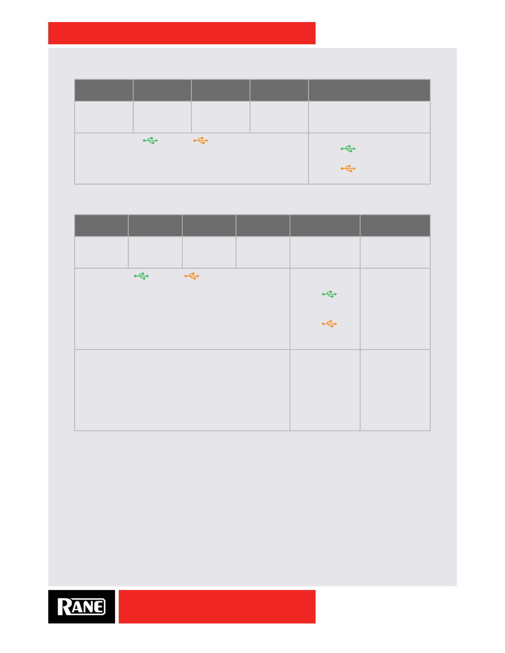
USB Playback Channels Assignment
Virtual Deck 3
USB Playback
Virtual Deck 1
USB Playback
Virtual Deck 2
USB Playback
Virtual Deck 4
USB Playback
FlexFX USB Insert Return
In USB audio
playback slots
1-2.
In USB audio
playback slots
3-4.
In USB audio
playback slots
5-6.
In USB audio
playback slots
7-8.
In USB audio playback slots 9-10.
Routed from either USB A or USB B depending on the
Deck Input channel source selection.
Route from either USB Port:
• Press A INSERT to route
from USB A.
• Press B INSERT to route
from USB B.
USB Record Channel Assignment
Deck 3
Record
Deck 1
Record
Deck 2
Record
Deck 4
Record
USB FlexFX Send Main Mix Record
In USB audio
record slots
1-2.
In USB audio
record slots
3-4.
In USB audio
record slots
5-6.
In USB audio
record slots
7-8.
In USB audio
record slots 9-10.
In USB audio
record slots 11-12.
Routed to either USB A or USB B depending on the
Deck Input channel source selection.
Routed to either
USB A or USB B:
• Press A
INSERT to route
to USB A.
• Press B
INSERT to route
to USB B
Broadcast to both
USB A and USB B
at all times.
In either the Shift Options or Control Panel, select one source:
1. Phono / CD pre-source selector (default). This must be
selected to use DVS (digital vinyl system).
2. Deck Post-fader (may be used for multichannel recording
when not using DVS).
These can be changed in the "Deck 1-4 Input Channel
Options Menu" on page 25, or the "Deck Inputs 1-4
Screen" on page 28.
USB Record is the
Send on the USB
Insert located in
the FlexFX Loop.
In the Driver
Control Panel,
select one of three
sources.
• Main Mix
(default).
• Mic 1.
• Mic 2.

OWNER’S MANUAL
24
SIXTY-FOUR
Shift Options
Several menus are available on the mixer to set preferences. Available menus are indicated with a gray up
arrow. To select a menu, press and hold the Shift button and then press the desired menu key.
Ext. Insert Options Menu
This menu sets the sensitivity of the external
analog insert to +4 dBu or -10 dBV. Use the
+4 dBu setting when a device operating at
4 Vrms or more is connected to the external
FlexFX Loop. Use the -10 dBV setting when
connecting lower voltage devices with RCA
connectors. The overall loop gain remains unchanged for both settings. Push the Beat joystick up/down to
select the desired setting then press the joystick to keep the selection. Press any effect button or the Shift
button to exit the menu.
Filter Effect Options Menu
The Filter menu allows choosing one of four
lter types. Move the Beat joystick up/down
to select the desired lter type then press the
joystick down to keep the selection. The Low-
sync Filters sync to BPM at the low point of the
sweep, and the High-sync Filters sync to BPM
at the high point of the sweep. Press any effect button or the Shift button to exit the menu.
• Low-pass Filter Low-sync.
• Low-pass Filter High-sync.
• High-pass Filter Low-sync.
• High-pass Filter High-sync.
Flanger Effect Options Menu
The Flanger menu allows the choice of positive
or negative feedback. Move the Beat joystick
up/down to highlight the desired feedback
type then press the joystick down to keep the
selection. Press any effect button or the Shift
button to exit the menu.
Echo Effect Options Menu
The Echo menu allows selection of four echo
effects:
• Echo.
• Echo with high-pass lter.
• Hold Echo.
• Hold Echo with high-pass lter.
Move the Beat joystick up/down to highlight the desired echo type then press the joystick
down to keep the selection. For the high-pass Echo and high-pass Hold Echo, adjust the lter
corner frequency by rotating the Time encoder, as it is displayed in the menu. Press any effect
button or the Shift button to exit the menu.
EXTERNAL INSERT
… +4 dBu
-10 dBV
SHIFT EXT. INSERT
LP FILTER LO
… LP FILTER HI
HP FILTER LO
HP FILTER LO
SHIFT
FILTER
FLANGER -Fb
… FLANGER +Fb
SHIFT
FLANGER
ECHO
… ECHO 81 Hz
HOLD ECHO
HD ECHO 120 Hz
SHIFT
ECHO

OWNER’S MANUAL
25
SIXTY-FOUR
Deck 1-4 Input Channel Options Menu
A menu is available for each deck input
channel. Press and hold the Shift button then
press the Cue button of an input channel. This
menu allows you to select 1 of 2 USB record
sources and set the resonance of the Filter.
Record options are:
• Pre-selector PH/CD input source (required for DVS).
• Post-fader audio for a channel.
Move the Beat joystick up/down to highlight the desired record source, then press the joystick
down to keep the selection. The PH/CD input must be selected for DVS operation.
Resonance is shown on the bar graph, and adjusted with the Time encoder.
High resonance results in a zippy whistle sound with high peaking of the signal at the corner frequency.
High resonance is typically used as an effect. A low resonance settings has no peaking and is typically
used for mixing. Press any effect button or the Shift button to exit the menu.
Main Mix Options Menu
This menu contains two options: USB record
source for USB audio slots 11-12, and the Main
Out Mono on/off.
• To change the Record source, move the
Beat joystick up/down to highlight the
desired source then press the joystick down
to keep the selection.
• To set the Stereo/Mono mode, use the Beat joystick to highlight the Mono item and press the joystick to
toggle Mono on or off.
Press any effect button or the Shift button to exit the menu.
Mixer Shift Functions
In addition to the menu selections, the Shift button also accesses alternate functions for other buttons.
MIDI Start/Stop
Hold the Shift button and press Tap to toggle
MIDI Start/Stop messages. MIDI Start is a
system real time message instructing devices
to start playing a sequence. MIDI Stop tells
devices to stop playing the sequence.
Nudge
Hold the Shift button and use the Beat
joystick to “Nudge” the outgoing MIDI beat
clock BPM up or down. MIDI beat clock is a
system real time message sent 24 times per
quarter note.
BPM Adjust
Hold the Shift button and turn the Time
encoder to adjust the BPM to a specic value.
… REC PH/CD-1
REC DECK1 POST
FILTER RESONANCE
SHIFT
CUE
… REC MAIN
REC MIC-1
REC MIC-2
MAIN OUT MONO
SHIFT
SPLIT CUE
START / STOP
SHIFT
TAP

OWNER’S MANUAL
26
SIXTY-FOUR
DJ Changeover
One of the biggest challenges of digital DJing has been seamlessly changing over from one DJ to the
next and playing back-to-back DJ sets. Now, with the next-level architecture of the Sixty-Four mixer,
changeover between digital DJs has never been easier.
If you’ve swapped between DJs using the Sixty-Two mixer, swapping with the Sixty-Four is done exactly
the same way. It's like a four-channel Sixty-Two. Another innovative feature of both mixers is MIDI routing.
When you assign a channel Input Source switch to your computer, MIDI follows along with the audio
automatically. This means two DJs can share the mixer, MIDI controls and all, without interference or
needing to manually toggle MIDI controls.
Deck Changeover Controls
At the top of each input channel is the Source Selector to switch input sources. If your computer is
connected to USB port A, switch a channel Source Select knob to USB A, and the mixer assigns the
corresponding Virtual Deck to that channel for audio playback. For example, assigning all four channels to
USB A1-A4, assigns all four virtual decks to the computer connected to USB port A.
The same applies to USB port B. If your computer is connected to USB port B, switching a channel
Source Select knob to USB B, assigns the corresponding virtual deck to that channel for audio playback.
When two DJs are connected to the Sixty-Four, they can quickly swap deck control between computers
using the Source Select knobs. Any of the four virtual decks can be swapped back and forth with a simple
knob twist. Nice and easy, just the way we intended.
The DJ Changeover Walkthrough
In the scenario below, one DJ, let’s call him DJ A, is already connected to the Sixty-Four using either
USB port A or B. With DJ A’s computer already connected to the Sixty-Four and playing music, do the
following:
1. Connect your computer to the unused USB port on the Sixty-Four.
2. Switch the Input Source on a non-playing input channel to the USB source of your computer.
3. Play a track on this Deck and mix it in when you're ready — audio from both computers are in the mix.
4. Fade out the audio playing from DJ A’s computer to the audio playing from your computer.
5. Assign the Input Source for the remaining free mixer channel(s) to your computer and continue DJing.
When DJ A is done, disconnect his computer from the USB port. If you’re back-to-back mixing with DJ A,
keep the computer connected and perform the same swapping instructions to regain deck control.
Enhancing Back-to-Back Mixing with the USB Insert
To enhance your back-to-back mixing experience, the Sixty-Four is equipped with two USB effect
inserts. The USB Inserts allow you to route audio from the Sixty-Four back to your computer for post-
fader effects. Now, with two USB Inserts, both DJs can quickly route audio back to their computers using
independent inserts for USB A and B. This gives both DJs the exibility to swap insert audio routing as
easily as swapping decks.

OWNER’S MANUAL
27
SIXTY-FOUR
Rane Drivers
The Serato DJ installer includes Core Audio (Mac) and ASIO (PC) drivers that allow your Rane Sixty-Four
to use other popular DJ and DAW audio applications. Once installed, you will have the option to select the
Sixty-Four’s inputs and outputs in the audio settings in these programs.
ASIO (Windows)
The Sixty-Four comes with a low-latency ASIO device driver on the installation CD to interface with
Serato DJ and other 3rd-party software applications on Windows operating systems. Multi-client ASIO
allows different audio software applications to simultaneously stream audio to and from the Sixty-Four.
If the same playback channel is selected in more than one application, the driver mixes the audio from
the applications before streaming it to the device. The driver Control Panel may be launched from the
Windows Control Panel. Select Start > Control Panel > Rane Sixty-Four.
Core Audio (Macintosh)
The Sixty-Four uses a low-latency Core Audio device driver on the installation CD to interface with Serato
DJ and other 3rd-party software applications on Macintosh operating systems. Core Audio allows audio
software applications to simultaneously stream audio to and from the Sixty-Four. To launch the Sixty-Four
driver Control Panel, open the System Preferences window. Locate the Sixty-Four in the “Other” section
and click the Sixty-Four icon.
NOTE: Settings are saved in the mixer. The control panel for Windows or Macintosh is updated with the
mixer’s settings. Therefore, when you connect to a different Sixty-Four Mixer, it's saved settings override
your previous Control Panel settings.
Preferences Screen
Select the Main Mix, Mic 1 or Mic 2 as the USB
11-12 Record source.
Main Mix Out can be set to Stereo or Mono.
USB Port Status indicates the connection status
of the two USB ports.
The control allows the USB buffer Buffer Size
to be increased or decreased. This control is
in the Rane driver in Windows (as shown). In
Mac systems, the buffer control is in the Serato DJ setup screen and does not appear here. The Sixty-
Four drivers are designed to run at latencies as low as 5 milliseconds round-trip. However, computer
performance and available resources (number of applications running) may adversely affect the
computer’s ability to stream audio reliably. If pops and clicks are heard in the USB audio, try increasing
the buffer size to eliminate them. With ASIO, total round-trip latency is equal to Buffer Size plus device
latency. With Core Audio, total round-trip latency is equal to Buffer Size plus software application buffer
latency, plus device latency. Device latency is 2.26 ms.
The rmware version currently installed in the Sixty-Four is shown. If the Sixty-Four rmware installed
on your computer is newer than the rmware in your Sixty-Four, the Update Device Firmware panel is
enabled. Pressing the Update Device Firmware button updates the Sixty-Four rmware to the new
version. Check for a Firmware Update after any Serato DJ software updates.

OWNER’S MANUAL
28
SIXTY-FOUR
Deck Inputs 1-4 Screen
There is one panel for each input channel on the
mixer. Each Deck panel controls these functions:
Analog Input Source: The analog input for each
channel may be set for Line level (CD) or Phono
level (PH) using a switch on the rear of the mixer.
The control panel shows the mode selected on the
mixer for each of the four inputs. This mode can
only be changed on the mixer.
Phono Sensitivity: If Phono Input is selected on the mixer (as shown for Deck 3) the Phono Sensitivity
adjustment appears in the panel. Click the down-arrow to display a list of 16 sensitivity settings between
2.5 mV and 10 mV in 0.5 mV steps. The default is 5 mV. Set the Phono Sensitivity to the same level of your
cartridge (see your cartridge documentation for the correct value). Another method is to match the level of
a CD on another input.
Filter Resonance: Each input channel has a Filter knob that provides high-pass and low-pass ltering.
Filter resonance controls the “peak” of the lter cutoff frequency. The Low setting provides the smoothest
Filter without adding gain. The High setting adds accent to frequencies near the Filter cutoff point by
adding about 12 dB of gain. Adding gain in a narrow peak around the cutoff frequency adds a “zippy
whistle” effect to audio as the Filter is swept. The default is 5 dB.
USB Record Source: These controls select one of two sources for each input channel as the USB record
source. When DVS is not used, a record source The PH / CD source must be selected for DVS control.
may be set to Post-fader to allow multi-channel recording of a set.
Effects Screen
The panel selects the lter type and sync Filter
mode:
• High-pass Filter with high-frequency sync.
• High-pass Filter with low-frequency sync.
• Low-pass Filter with high-frequency sync.
• Low-pass Filter with low-frequency sync.
The Flanger panel selects a feedback mode:
• Positive feedback.
• Negative feedback.
The panel selects one of four echo modes. Echo
• Echo with no feedback lter and adjustable recirculation 0 to 70%.
• Hold Echo with no feedback lter and adjustable recirculation of 0% to 100%.
• Low-cut Echo with adjustable feedback lter and adjustable recirculation 0 to 70%.
• Low-cut Hold Echo with adjustable feedback lter and adjustable recirculation of 0% to 100%.
The sliders set the low-cut lter cutoff frequency•
The panel has two options. We recommend the +4 dBu setting unless you insert a low-Analog Insert
voltage device using RCA connectors.
• +4 dBu.
• -10 dBV.

OWNER’S MANUAL
29
SIXTY-FOUR
MIDI Conguration Screen
• When Receive MIDI Beat Clock is checked, the
mixer receives MIDI real time system messages.
• When Send MIDI Beat Clock is checked, the
mixer sends MIDI real time system messages.
• When User Button Lighting is checked, the
mixer will not automatically light button LEDs for
momentary presses. Enable this option if you
wish to send MIDI commands to the mixer from
3rd-party software to control button LEDs.
Factory Defaults
To reset a Sixty-Four Mixer to its default settings:
• Power off the Sixty-Four.
• Push both Deck 1 FlexFX and Deck 2 FlexFX buttons at the same time.
• While holding these buttons down, power on the Sixty-Four.
• Immediately after fading up, the FlexFX lights ash bright one time, indicating a successful reset.
To check the mixer's current rmware version, press and hold Shift then press Non PGM MIDI.

OWNER’S MANUAL
30
SIXTY-FOUR
MIDI Mapping
Mic Bypass Mode
All controls on the mixer are MIDI mappable, including the Mic sections. If you do not use the Mic
sections, you can independently bypass the controls so they do not affect audio, and only output their
MIDI changes. This allows you to map the Mic controls to functions in software, such as effects, and not
have to worry about introducing noise in your mix from a oating Mic input.
To toggle Mic Bypass Mode, hold the Shift button and press the Mic On button
for the Mic section you wish to bypass. That button will start ashing lightly,
indicating those audio controls are now bypassed and are only outputting MIDI
changes. The Mic On and FlexFX buttons, as well as the Level, Pan, and Tone
controls are affected by this mode. While bypassed, the FlexFX and Mic On
buttons will ash with momentary button presses, but the LED state cannot be
set from software like the side strip controls. Holding the Shift button and pressing the Mic On button
again will exit Mic Bypass Mode, returning the Mic section to regular operation. The Mic On button will
return to the ‘off’ state.
Be sure to reset the Level, Pan, and Tone controls to appropriate values before switching the Mic back on.
Top Panel Map
In the following diagrams, green equals Control Change and blue equals Note On/
Off. All control changes are single precision, 0x00 to 0x7F (0 to 127 dec). As noted,
all software controls on the two side strips are routed to USB Port A or USB Port B
according to Deck input selectors. All other controls dedicated to mixer functions are
sent to USB Port A or USB Port B according to the Non PGM MIDI button located
under the Main Mix meter. Toggle between for USB Port A and for USB Port B.Green Orange
SHIFT
ON
MIC
BA
NON PGM MIDI
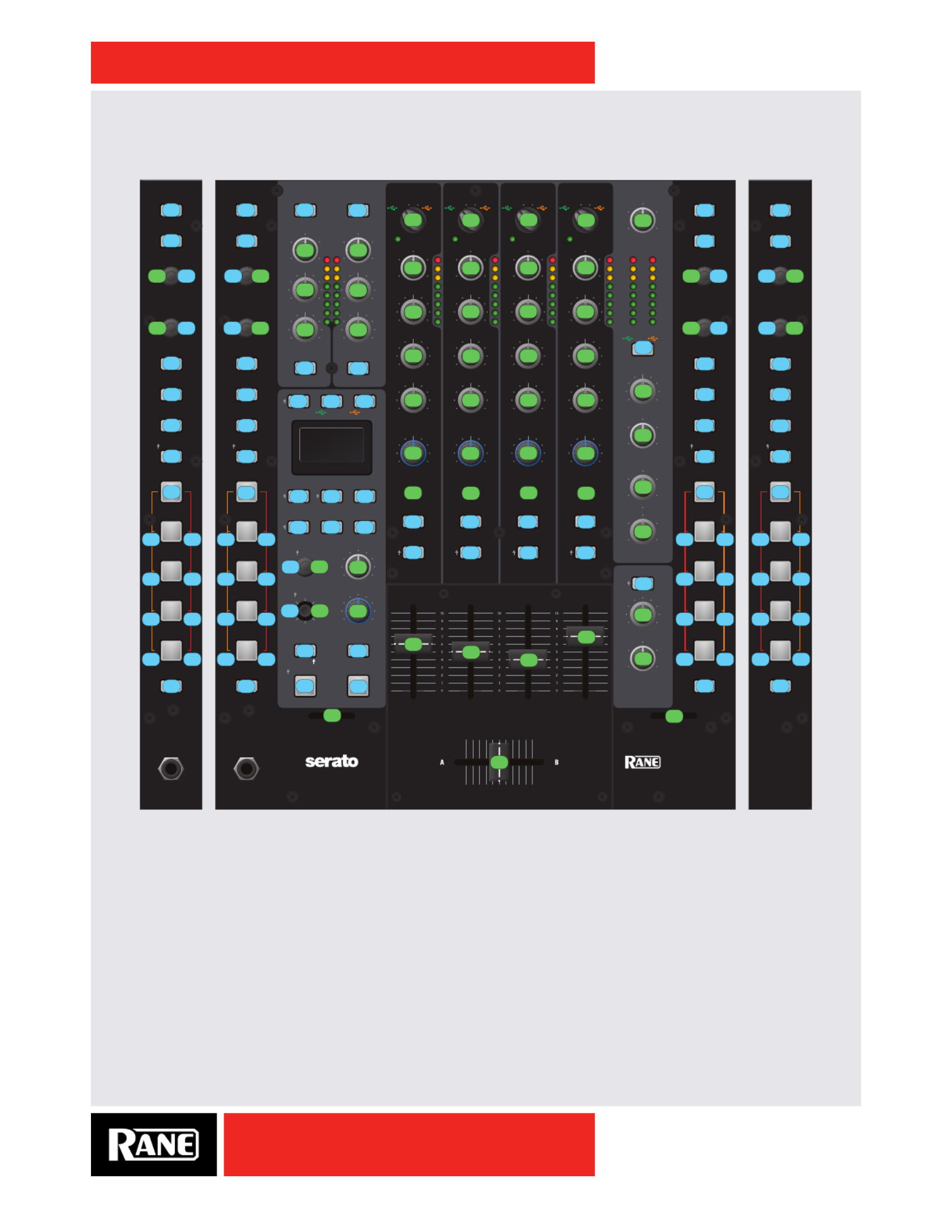
OWNER’S MANUAL
31
SIXTY-FOUR
Front Panel MIDI Controls
Controlling button backlighting is only possible for software controls. The MIDI Note ON/OFF number
for button backlighting is the same as for the associated switch note on/off. The acceleration value
determines the color and intensity of the backlight as follows:
• LEDs OFF: 0x00 – 0x1E
• Primary Color Dim: 0x1F – 0x2F
• Primary Color Full: 0x30 – 0x4E
• Secondary Color Dim: 0x4F – 0x5F
• Secondary Color Full: 0x60 – 0x7F
3B 2B 4B
B
1B
B INSERT
3A 2A 4A
A
1A
A INSERT
10
0
2
4
8
6
HIGHLOW
10
0
2
4
8
6
10
0
2
4
8
6
HIGHLOW
10
0
2
4
8
6
10
0
2
4
8
6
10
0
2
4
8
6
10
0
2
4
8
6
10
0
2
4
8
6
10
0
2
4
8
6
10
0
2
4
8
6
10
0
2
4
8
6
OL
+6
+3
0
-3
-12
-6
-18
RIGHTLEFT
MAINCUE
RIGHT
LEFT
RIGH
LEFT
+6
OFF
+6
OFF
+6
OFF
HIG
LOW
+6
OFF
+6
OFF
+6
OFF
HIG
LOW
+6
OFF
+6
OFF
+6
OFF
HIG
LOW
+6
OFF
+6
OFF
+6
OFF
HIG
LOW
MA
MI
MA
MI
BPM
START / STOP
NU DGE
LAYER 1
(CUE / LOOP)
(SAMPLES)
SYNC OFF
(CUE / LOOP)
(SAMPLES)
SYNC OFF
LAYER 2
LAYER 3
LAYER 4
LAYER 1
(CUE / LOOP)
(SAMPLES)
SYNC OFF
LAYER 2
LAYER 3
LAYER 4
LAYER 1
LAYER 2
LAYER 3
LAYER 4
(CUE / LOOP)
(SAMPLES)
SYNC OFF
LAYER 1
LAYER 2
LAYER 3
LAYER 4
SCROLL / LOAD
LOOP
SYNC
LAYER
SCROLL / LOAD
LOOP
ROLL
SLIP
LOOP
SYNC
LOOP
ROLL
SLIP
NON PGM MIDI
TONE TONE
FLEXFX FLEXFX
SHIFT CUE
CUE
EXT. INSERT
PH/CD 3 AUX
CONTROL
CUE
PH/CD 2 AUX
CONTROL
CUE
PH/CD 4 AUX
CONTROL
MAIN MIX
CUE
PH/CD 1 AUX
CONTROL
BOOTH
PHONES
SESSION OUT
SESSION IN
BALANCE
PAN
SPLIT CUE
LEVEL
A B
MID
LOW
FILTER
LEVEL LEVEL
LEVEL
PANPAN
HIGH
LEVELTIME
DEPTH
FLEXFX
CROSSFADER
FILTER
FLEXFX
BEAT
BANK
1 5
2 6
3 7
4 8
LAYER
5 1
6 2
7 3
8 4
ONTAP
PHASERFLANGER
ROBOT
FADER CONTOUR CROSSFADER CONTOUR
PHONES
ECHO REVERB
POST
A B
MID
LOW
FILTER
LEVEL
HIGH
FLEXFX
CROSSFADER
POST
A B
MID
LOW
FILTER
LEVEL
HIGH
FLEXFX
CROSSFADER
POST
A B
MID
LOW
FILTER
LEVEL
HIGH
FLEXFX
CROSSFADER
POST
DECK 3 / 1 ON ON
MIC 1 MIC 2
3124
TAB
SCROLL / LOAD
LOOP
SYNC
LAYER
LOOP
ROLL
SLIP
BANK
1 5
2 6
3 7
4 8
PHONES
DECK 3 / 1
TAB
DECK 2 / 4
TAB
BANK
SIXTY-FOUR
SCROLL / LOAD
LOOP
SYNC
LOOP
ROLL
SLIP
LAYER
5 1
6 2
7 3
8 4
DECK 2 / 4
TAB
BANK
DECK 3 DECK 1 DECK 2 DECK 4
0A
2A 2A
2B
7B2C
7D
19 6C
6D 1C
6E 1E
6F 1D
13 79
01 03
12 14
17 10
16 21
15 27
68 64
69 20
62 26
63 30
4C 4E
35 49
54 4A
56 4B
6B 65
36 66
55 67
57 6A
74 74
33 33
34 7E
71 3F
72 3D
73 39
4F 7A
60 61
77 77
29 28
22 58
5B 1F 76
0C 0B 0A
0D 09 08
75 04
05 00
45
44 43
46
42
47
41
48
38
78
10
64
11 2C
4C
58 46
5E 40
60
01
02 14
07 6F
0B7C3712
2D703A13
74
59
65
4D
47
41
78
53
75
5A
66
4E
48
42
79
54
76
5B
67
4F
49
43
7A
55
77
5C
68
50
4A
44
7B
56
63
69
45
57
4B
51
5D
00
62
02
DECK 3
CONTROLS
DECK 1
CONTROLS
DECK 2
CONTROLS
DECK 4
CONTROLS

OWNER’S MANUAL
32
SIXTY-FOUR
MIDI controllable backlight buttons and LED Colors are as follows: (Primary/Secondary)
• TAB: Green/Yellow
• LOOP: Green/Orange
• ROLL: Green/Orange
• SLIP: Green/Orange
• SYNC: Red/Orange
• TRIGGER 1/5: Green/Yellow
• TRIGGER 2/6: Green/Yellow
• TRIGGER 3/7: Green/Yellow
• TRIGGER 4/8: Green/Yellow
Rear Panel MIDI Controls
Control Panel MIDI (Mixer Menu Controls)
Control change numbers for items in the mixer menus are shared with the corresponding controls in the
driver control panel.
MAIN OU
SEND
PHONO
GROUND
MIC 1
MIC 2
SESSION
AUX
ANALOG INPU
MIC INPUT
LEFT (MONO
100-240V 50/60 Hz 15 WATTS
LEFT
RIGHT
RANE CORPORATI
RIGHT
RETURN
SESSION
FLEXFX LO
LEFT
RIGHT
USB A
USB B
BOOTH OU
LEFT
RIGH
IN
IN
OUT
R
L
1
3
R
L
4
IN
OUT
S/PDIF
2
PH - CD
PH - CD
OFF - +48
PH - CD
PH - CD
R
L
MIC - LINE
SIXTY-FOUR
70717273
21
31
2E
15 1E
18
17 1A 1D 20
1B
70 7371 72
16 1F19 1C
29
2A
2F
28
2B
27

OWNER’S MANUAL
33
SIXTY-FOUR
MIDI Implementation
Serato DJ MIDI Control only supports:
• Note On/Off
• Standard 7-bit CC (Control Change)
There are two categories of MIDI controls:
Red: Dedicated mixer controls are read only and not affected by MIDI in commands. A user is not able
to control mixer functions via MIDI and is unable to change the color or intensity of an LED under one
of these mixer controls. Users are able to use MIDI out for these controls to trigger or control software
functions.
Green: MIDI controls on the mixer dedicated to Serato DJ or 3rd-party DAW control. These controls are
read/write and a user is able to control the color and intensity of LEDs under these buttons.
MIDI Note ON/OFF Chart
The note number for an LED indicator under a button is the same as for the button.
The color and brightness of an LED is determined by the velocity as follows:
• 0-30 0x00-0x1E Off
• 31-47 0x1F-0x2F Primary Dim
• 48-78 0x30-0x4E Primary Full
• 79-95 0x4F-0x5F Secondary Dim
• 96-127 0x60-0x7F Secondary Full
Note # (Hex) Symbol Function LED States
0 0x00 FX_ON_NOTE FlexFX On Not Permitted
1 0x01 L_BANKS_NOTE Deck 3 Bank Not Permitted
2 0x02 FX_ENC_SW_NOTE FlexFX Time (SW) Not Applicable
3 0x03 L_BANKS_ALT_NOTE Deck 1 Bank Not Permitted
4 0x04 FX_CUE_NOTE FlexFX Cue Not Permitted
5 0x05 FX_TAP_NOTE FlexFX Tap Not Permitted
7 0x07 FX_JOY_SW_NOTE FlexFX Beat (SW) Not Applicable
8 0x08 FX_FX6_NOTE FlexFX Reverb Not Permitted
9 0x09 FX_FX5_NOTE FlexFX Robot Not Permitted
10 0x0A FX_FX3_NOTE FlexFX Phaser Not Permitted
11 0x0B FX_FX2_NOTE FlexFX Flanger Not Permitted
12 0x0C FX_FX1_NOTE FlexFX Filter Not Permitted
13 0x0D FX_FX4_NOTE FlexFX Echo Not Permitted
14 0x0E FX_JOY_NORTH_NOTE FlexFX Beat North Not Applicable
15 0x0F FX_JOY_SOUTH_NOTE FlexFX Beat South Not Applicable
16 0x10 L_CUE_6_NOTE Deck 3 Trigger 6 PRI – Green / SEC – Yellow
16 0x10 FX_JOY_EAST_NOTE FlexFX Beat East Not Applicable
17 0x11 FX_JOY_WEST_NOTE FlexFX Beat West Not Applicable
18 0x12 L_CUE_1_NOTE Deck 3 Trigger 1 PRI – Green / SEC – Yellow
19 0x13 L_SYNC_NOTE Deck 3 Sync PRI – Red / SEC – Orange
20 Deck 3 Trigger 5 PRI – Green / SEC – Yellow0x14 L_CUE_5_NOTE
21 0x15 L_CUE_4_NOTE Deck 3 Trigger 4 PRI – Green / SEC – Yellow
22 0x16 L_CUE_3_NOTE Deck 3 Trigger 3 PRI – Green / SEC – Yellow

OWNER’S MANUAL
34
SIXTY-FOUR
23 0x17 L_CUE_2_NOTE Deck 3 Trigger 2 PRI – Green / SEC – Yellow
25 0x19 L_ENC2_SW_NOTE Deck 3 Loop Load Not Applicable
28 0x1C L_LOOP_ALT_NOTE Deck 1 Loop PRI – Green / SEC – Orange
29 0x1D L_SLIP_ALT_NOTE Deck 1 Slip PRI – Green / SEC – Orange
30 0x1E L_ROLL_ALT_NOTE Deck 1 Roll PRI – Green / SEC – Orange
31 0x1F USB_A_INS_NOTE USB A Insert Not Permitted
32 0x20 Deck 1 Trigger 6 PRI – Green / SEC – YellowL_CUE_6_ALT_NOTE
33 0x21 L_CUE_7_NOTE Deck 3 Trigger 7 PRI – Green / SEC – Yellow
34 0x22 MIC1_FX_NOTE Mic 1 FlexFX Not Permitted
38 0x26 L_CUE_7_ALT_NOTE Deck 1 Trigger 7 PRI – Green / SEC – Yellow
39 0x27 L_CUE_8_NOTE Deck 3 Trigger 8 PRI – Green / SEC – Yellow
40 0x28 MIC2_ON_NOTE Mic 2 On Not Permitted
41 0x29 MIC1_ON_NOTE Mic 1 On Not Permitted
42 0x2A L_DECK_NOTE Deck 3/1 Not Permitted
43 0x2B L_TAB_NOTE Deck 3 Tab PRI – Green / SEC – Orange
44 0x2C L_ENC1_SW_NOTE Deck 3 Load Not Applicable
48 0x30 L_CUE_8_ALT_NOTE Deck 1 Trigger 8 PRI – Green / SEC – Yellow
51 0x33 R_DECK_NOTE Deck 2/4 Not Permitted
52 0x34 R_TAB_NOTE Deck 2 Tab PRI – Green / SEC – Orange
53 0x35 R_CUE_6_NOTE Deck 2 Trigger 6 PRI – Green / SEC – Yellow
54 0x36 R_CUE_6_ALT_NOTE Deck 4 Trigger 6 PRI – Green / SEC – Yellow
55 0x37 R_ENC1_SW_NOTE Deck 2 Load Not Applicable
56 SPLIT_CUE_NOTE0x38 Split Cue Not Permitted
57 0x39 R_SLIP_ALT_NOTE Deck 4 Slip PRI – Green / SEC – Orange
58 0x3A R_ENC2_SW_NOTE Deck 2 Loop Load Not Applicable
61 0x3D R_ROLL_ALT_NOTE Deck 4 Roll PRI – Green / SEC – Orange
63 0x3F R_LOOP_ALT_NOTE Deck 4 Loop PRI – Green / SEC – Orange
65 0x41 PGM4_FX_NOTE Deck 4 FlexFX Not Permitted
66 0x42 PGM3_FX_NOTE Deck 2 FlexFX Not Permitted
67 0x43 PGM2_FX_NOTE Deck 1 FlexFX Not Permitted
68 0x44 PGM1_FX_NOTE Deck 3 FlexFX Not Permitted
69 0x45 PGM1_CUE_NOTE Deck 3 Cue Not Permitted
70 0x46 PGM2_CUE_NOTE Deck 1 Cue Not Permitted
71 0x47 PGM3_CUE_NOTE Deck 2 Cue Not Permitted
72 0x48 PGM4_CUE_NOTE Deck 4 Cue Not Permitted
73 0x49 R_CUE_2_NOTE Deck 2 Trigger 2 PRI – Green / SEC – Yellow
74 0x4A R_CUE_3_NOTE Deck 2 Trigger 3 PRI – Green / SEC – Yellow
75 0x4B R_CUE_4_NOTE Deck 2 Trigger 4 PRI – Green / SEC – Yellow
76 0x4C R_CUE_5_NOTE Deck 2 Trigger 5 PRI – Green / SEC – Yellow
78 0x4E R_CUE_1_NOTE Deck 2 Trigger 1 PRI – Green / SEC – Yellow
79 0x4F R_SYNC_NOTE Deck 2 Sync PRI – Red / SEC – Orange
80 0x50 PGM1_CNTRL_NOTE Deck 3 Control Status ON – Controlled by Left Strip
OFF – No Control of Deck

OWNER’S MANUAL
36
SIXTY-FOUR
MIDI Control Change Chart
Note # (Hex) Symbol Function Values
0 0x00 XFADER_NUM Crossfader 0x00-0x7F
1 0x01 FX_DEPTH_NUM FlexFX Depth 0x00-0x7F
2 0x02 Deck Fader ContourPGM_CURVE_NUM 0x00-0x7F
10 0x0A L_ENC_1_ALT_NUM Deck 1 Scroll/Load 2’s Complement from 64 / Relative
(Binary Offset)
11 0x0B R_ENC_1_ALT_NUM Deck 4 Scroll/Load 2’s Complement from 64 / Relative
(Binary Offset)
16 0x10 L_ENC_1_NUM Deck 3 Scroll/Load 2’s Complement from 64 / Relative
(Binary Offset)
17 0x11 L_ENC_2_NUM Deck 3 Loop Scroll 2’s Complement from 64 / Relative
(Binary Offset)
18 0x12 R_ENC_1_NUM Deck 2 Scroll/Load 2’s Complement from 64 / Relative
(Binary Offset)
19 0x13 R_ENC_2_NUM Deck 2 Loop Scroll 2’s Complement from 64 / Relative
(Binary Offset)
20 2’s Complement from 64 / Relative 0x14 FX_ENCODER_NUM FlexFX Time
(Binary Offset)
21 0x15 A1_PHONO_SENS_NUM PH/CD-3 Phono
Sensitivity
Value Sensitivity (mV) dB
0x00 2.5 16.04
0x01 3 14.46
0x02 3.5 12.12
0x03 4 11.96
0x04 4.5 10.94
0x05 5 (default) 10.02
0x06 5.5 9.19
0x07 6 8.44
0x08 6.5 7.74
0x09 7 7.1
0x0A 7.5 6.5
0x0B 8 5.94
0x0C 8.5 5.41
0x0D 9 4.92
0x0E 9.5 4.45
0x0F 10 4
22 0x16 PGM1_FILTER_RES_NUM Deck 3 Filter Resonance 0x00-0x7F, Low to High Resonance
23 0x17 PGM1_REC_SEL_NUM Deck 3 Record Select 0x01 – Record PH/CD-3
0x02 – Record Deck 3 Post
24 0x18 A2_PHONO_SENS_NUM PH/CD-1 Phono
Sensitivity
Same as PH/CD-3 Phono
Sensitivity
25 0x19 PGM2_FILTER_RES_NUM Deck 1 Filter Resonance 0x00-0x7F, Low to High Resonance
26 0x1A PGM2_REC_SEL_NUM Deck 1 Record Select 0x01 – Record PH/CD-1
0x02 – Record Deck 1 Post

OWNER’S MANUAL
37
SIXTY-FOUR
27 0x1B A3_PHONO_SENS_NUM PH/CD-2 Phono
Sensitivity
Same as PH/CD-3 Phono
Sensitivity
28 0x1C PGM3_FILTER_RES_NUM Deck 2 Filter Resonance 0x00-0x7F, Low to High Resonance
29 0x1D PGM3_REC_SEL_NUM Deck 2 Record Select 0x01 – Record PH/CD-2
0x02 – Record Deck 2 Post
30 0x1E A4_PHONO_SENS_NUM PH/CD-4 Phono
Sensitivity
Same as PH/CD-3 Phono
Sensitivity
31 0x1F PGM4_FILTER_RES_NUM Deck 4 Filter Resonance 0x00-0x7F, Low to High Resonance
32 0x20 PGM4_REC_SEL_NUM Deck 4 Record Select 0x01 – Record PH/CD-4
0x02 – Record Deck 4 Post
33 Main Record Select0x21 MAIN_REC_SEL_NUM 0x01 – Record Main Mix
0x02 – Record Mic 1
0x03 – Record Mic 2
38 0x26 DUCK_ECHO_HP_FREQ_NUM LC Duck Echo
Frequency
0x00-0x7F, 20 Hz-10 kHz
Uniform Octave Steps
39 0x27 FLANGER_TYPE_NUM Flanger Type Select 0x00-0x3F – Negative
0x40-0x7F – Positive
40 0x28 ECHO_TYPE_NUM Echo Type Select 0x00-0x1F – Echo
0x20-0x3F – High Pass Echo
0x40-0x5F – Hold Echo
0x60-0x7F – High Pass Hold Echo
41 0x29 FILTER_TYPE_NUM Filter Type Select 0x00-0x1F – Low Pass Sync Lo
0x20-0x3F – Low Pass Sync Hi
0x40-0x5F – High Pass Sync Lo
0x60-0x7F – High Pass Sync Hi
42 0x2A ECHO_HP_FREQ_NUM LC Echo Frequency 0x00-0x7F, 20 Hz-10 kHz
Uniform Octave Steps
43 0x2B HOLD_ECHO_HP_FREQ_NUM LC Hold Echo Frequency 0x00-0x7F, 20 Hz-10 kHz
Uniform Octave Steps
44 L_ENC_2_ALT_NUM0x2C Deck 1 Loop Scroll 2’s Complement from 64 / Relative
(Binary Offset)
45 0x2D R_ENC_2_ALT_NUM Deck 4 Loop Scroll 2’s Complement from 64 / Relative
(Binary Offset)
46 0x2E BUTTON_LIGHTING_NUM User Button Lighting 0x00-0x3F – User control disabled
0x40-0x7F – User control enabled
47 0x2F FX_EXT_INS_SENS_NUM External Insert
Sensitivity
0x00-0x3F – 4 dBu
0x40-0x7F – -10 dB
49 0x31 MAIN_OUT_MONO_NUM Main Out Mono 0x00-0x3F – Mono Off
0x40-0x7F – Mono On
53 0x35 USB_PORT_ID_NUM USB Port Status 0x00-0x3F – USB Port A
0x40-0x7F – USB Port B
54 0x36 USB_INSERT_STATE_NUM USB Insert Status 0x00 – None
0x01 – USB Insert A
0x02 – USB Insert B
64 0x40 MIC2_TONE_NUM Mic 2 Tone 0x00-0x7F

OWNER’S MANUAL
38
SIXTY-FOUR
65 0x41 PGM1_FILTER_NUM Deck 3 Filter 0x00-0x7F
66 0x42 PGM2_FILTER_NUM Deck 1 Filter 0x00-0x7F
67 0x43 PGM3_FILTER_NUM Deck 2 Filter 0x00-0x7F
68 0x44 PGM4_FILTER_NUM Deck 4 Filter 0x00-0x7F
69 0x45 SESSION_IN_NUM Session In Level 0x00-0x7F
70 0x46 MIC2_PAN_NUM Mic 2 Pan 0x00-0x7F
71 0x47 PGM1_LOW_NUM Deck 3 Low 0x00-0x7F
72 0x48 PGM2_LOW_NUM Deck 1 Low 0x00-0x7F
73 0x49 PGM3_LOW_NUM Deck 2 Low 0x00-0x7F
74 0x4A PGM4_LOW_NUM Deck 4 Low 0x00-0x7F
75 0x4B BOOTH_LEVEL_NUM Booth Level 0x00-0x7F
76 0x4C MIC2_LEVEL_NUM Mic 2 Level 0x00-0x7F
77 0x4D PGM1_MID_NUM Deck 3 Mid 0x00-0x7F
78 0x4E PGM2_MID_NUM Deck 1 Mid 0x00-0x7F
79 0x4F PGM3_MID_NUM Deck 2 Mid 0x00-0x7F
80 0x50 PGM4_MID_NUM Deck 4 Mid 0x00-0x7F
81 0x51 MAIN_BALANCE_NUM Main Balance 0x00-0x7F
83 0x53 PGM1_FADER_NUM Deck 3 Fader 0x00-0x7F
84 0x54 PGM2_FADER_NUM Deck 1 Fader 0x00-0x7F
85 0x55 PGM3_FADER_NUM Deck 2 Fader 0x00-0x7F
86 0x56 PGM4_FADER_NUM Deck 4 Fader 0x00-0x7F
87 0x57 SESSION_OUT_NUM Session Out Level 0x00-0x7F
88 0x58 MIC1_PAN_NUM Mic 1 Pan 0x00-0x7F
89 0x59 PGM1_LEVEL_NUM Deck 3 Level 0x00-0x7F
90 0x5A PGM2_LEVEL_NUM Deck 1 Level 0x00-0x7F
91 0x5B PGM3_LEVEL_NUM Deck 2 Level 0x00-0x7F
92 0x5C PGM4_LEVEL_NUM Deck 4 Level 0x00-0x7F
93 0x5D MAIN_LEVEL_NUM Main Level 0x00-0x7F
94 0x5E MIC1_TONE_NUM Mic 1 Tone 0x00-0x7F
96 0x60 FX_LEVEL_NUM FlexFX Loop Level 0x00-0x7F
98 0x62 XFADER_CONT_NUM Crossfader Contour 0x00-0x7F
99 0x63 PHONES_LEVEL_NUM Headphones Level 0x00-0x7F
100 0x64 MIC1_LEVEL_NUM Mic 1 Level 0x00-0x7F
101 0x65 PGM1_HIGH_NUM Deck 3 High 0x00-0x7F
102 0x66 PGM2_HIGH_NUM Deck 1 High 0x00-0x7F
103 0x67 PGM3_HIGH_NUM Deck 2 High 0x00-0x7F
104 0x68 PGM4_HIGH_NUM Deck 4 High 0x00-0x7F
105 0x69 CUE_PAN_NUM Cue Pan 0x00-0x7F
109 0x6D PGM4_LAYER_NUM Deck 4 Layer 0x00 – Layer 1
0x01 – Layer 2
0x02 – Layer 3
0x03 – Layer 4

OWNER’S MANUAL
39
SIXTY-FOUR
110 0x6E PGM3_LAYER_NUM Deck 3 Layer 0x00 – Layer 1
0x01 – Layer 2
0x02 – Layer 3
0x03 – Layer 4
112 0x70 INPUT_A1_TYPE_NUM PH/CD-1 Input Select 0x00 – Phono
0x01 – Line
113 0x71 INPUT_A2_TYPE_NUM PH/CD-2 Input Select 0x00 – Phono
0x01 – Line
114 0x72 INPUT_A3_TYPE_NUM PH/CD-3 Input Select 0x00 – Phono
0x01 – Line
115 0x73 INPUT_A4_TYPE_NUM PH/CD-4 Input Select 0x00 – Phono
0x01 – Line
116 0x74 PGM1_SRC_SEL_NUM Deck 3 Source Select 0x01 – USB-3A
0x02 – PH/CD-3
0x03 – Aux
0x04 – USB-3B
117 0x75 PGM2_SRC_SEL_NUM Deck 1 Source Select 0x01 – USB-1A
0x02 – PH/CD-1
0x03 – Aux
0x04 – USB-1B
118 0x76 PGM3_SRC_SEL_NUM Deck 2 Source Select 0x01 – USB-2A
0x02 – PH/CD-2
0x03 – Aux
0x04 – USB-2B
119 0x77 PGM4_SRC_SEL_NUM Deck 4 Source Select 0x01 – USB-4A
0x02 – PH/CD-4
0x03 – Aux
0x04 – USB-4B
120 0x78 PGM1_XSEL_NUM Deck 3 Crossfader
Assign
0x01 – Post
0x02 – A
0x03 – B
121 0x79 PGM2_XSEL_NUM Deck 1 Crossfader
Assign
0x01 – Post
0x02 – A
0x03 – B
122 0x7A PGM3_XSEL_NUM Deck 2 Crossfader
Assign
0x01 – Post
0x02 – A
0x03 – B
122 0x7A PGM1_LAYER_NUM Deck 1 Layer 0x00 – Layer 1
0x01 – Layer 2
0x02 – Layer 3
0x03 – Layer 4
123 0x7B PGM4_XSEL_NUM Deck 4 Crossfader
Assign
0x01 – Post
0x02 – A
0x03 – B
123 0x7B PGM2_LAYER_NUM Deck 2 Layer 0x00 – Layer 1
0x01 – Layer 2
0x02 – Layer 3
0x03 – Layer 4
Produkt Specifikationer
| Mærke: | Rane |
| Kategori: | Blandekonsol |
| Model: | Sixty-Four |
Har du brug for hjælp?
Hvis du har brug for hjælp til Rane Sixty-Four stil et spørgsmål nedenfor, og andre brugere vil svare dig
Blandekonsol Rane Manualer

11 Januar 2025
21 August 2024
19 August 2024
19 August 2024
19 August 2024
19 August 2024
18 August 2024
18 August 2024
18 August 2024
16 August 2024
Blandekonsol Manualer
- Blandekonsol Bosch
- Blandekonsol Gorenje
- Blandekonsol Philips
- Blandekonsol Concept
- Blandekonsol Audio-Technica
- Blandekonsol Electrolux
- Blandekonsol Peavey
- Blandekonsol Pioneer
- Blandekonsol TOA
- Blandekonsol Braun
- Blandekonsol Qtx
- Blandekonsol Melissa
- Blandekonsol Dynacord
- Blandekonsol Behringer
- Blandekonsol Kenwood
- Blandekonsol Korona
- Blandekonsol Roland
- Blandekonsol Golden Age Project
- Blandekonsol Pyle
- Blandekonsol Denon
- Blandekonsol Yamaha
- Blandekonsol Nedis
- Blandekonsol Emerio
- Blandekonsol Severin
- Blandekonsol Moulinex
- Blandekonsol Sunbeam
- Blandekonsol LD Systems
- Blandekonsol Auna
- Blandekonsol Hyundai
- Blandekonsol Pyle Pro
- Blandekonsol JBL
- Blandekonsol AKAI
- Blandekonsol TriStar
- Blandekonsol RCF
- Blandekonsol Chandler
- Blandekonsol Adler
- Blandekonsol Blaupunkt
- Blandekonsol Alpina
- Blandekonsol Clatronic
- Blandekonsol Skytec
- Blandekonsol Fagor
- Blandekonsol König
- Blandekonsol Bifinett
- Blandekonsol Bomann
- Blandekonsol Redmond
- Blandekonsol Ariete
- Blandekonsol KitchenAid
- Blandekonsol Zelmer
- Blandekonsol Bose
- Blandekonsol EnVivo
- Blandekonsol Comfee
- Blandekonsol Cuisinart
- Blandekonsol Primo
- Blandekonsol BeamZ
- Blandekonsol Alecto
- Blandekonsol Taurus
- Blandekonsol Exquisit
- Blandekonsol PreSonus
- Blandekonsol Hanseatic
- Blandekonsol Domo
- Blandekonsol Tascam
- Blandekonsol Bogen
- Blandekonsol Omnitronic
- Blandekonsol Zoom
- Blandekonsol TC Helicon
- Blandekonsol HQ Power
- Blandekonsol Korg
- Blandekonsol Fredenstein
- Blandekonsol Inventum
- Blandekonsol Soundcraft
- Blandekonsol American Audio
- Blandekonsol ART
- Blandekonsol Monacor
- Blandekonsol Samson
- Blandekonsol ION
- Blandekonsol Numark
- Blandekonsol Allen & Heath
- Blandekonsol DBX
- Blandekonsol Warm Audio
- Blandekonsol TeachLogic
- Blandekonsol Midas
- Blandekonsol Radial Engineering
- Blandekonsol Fritel
- Blandekonsol Alesis
- Blandekonsol Alto
- Blandekonsol Proline
- Blandekonsol Waves
- Blandekonsol Hobart
- Blandekonsol Stirling
- Blandekonsol APart
- Blandekonsol Turmix
- Blandekonsol Kramer
- Blandekonsol NutriBullet
- Blandekonsol QSC
- Blandekonsol Kalorik
- Blandekonsol Martin
- Blandekonsol Audiophony
- Blandekonsol Gemini
- Blandekonsol Solid State Logic
- Blandekonsol Citronic
- Blandekonsol RDL
- Blandekonsol Solac
- Blandekonsol Roadstar
- Blandekonsol Sound Devices
- Blandekonsol Wharfedale
- Blandekonsol Efbe-Schott
- Blandekonsol Mackie
- Blandekonsol Reloop
- Blandekonsol Team
- Blandekonsol ATen
- Blandekonsol Shure
- Blandekonsol Power Dynamics
- Blandekonsol Arendo
- Blandekonsol Vonyx
- Blandekonsol Speco Technologies
- Blandekonsol Boss
- Blandekonsol Klark Teknik
- Blandekonsol Bestron
- Blandekonsol Philco
- Blandekonsol Crestron
- Blandekonsol DAP-Audio
- Blandekonsol SPL
- Blandekonsol Showtec
- Blandekonsol Russound
- Blandekonsol Crown
- Blandekonsol Rolls
- Blandekonsol Adastra
- Blandekonsol Atlas Sound
- Blandekonsol Heritage Audio
- Blandekonsol Dash
- Blandekonsol Ibiza Sound
- Blandekonsol Alfatron
- Blandekonsol Flama
- Blandekonsol Sonifex
- Blandekonsol OWI
- Blandekonsol Dangerous Music
- Blandekonsol Nektar
- Blandekonsol Allen-Heath
- Blandekonsol Alto Professional
- Blandekonsol ADB
- Blandekonsol Nordland
- Blandekonsol Marquant
- Blandekonsol Valcom
- Blandekonsol Blaze
- Blandekonsol Swissonic
- Blandekonsol Aviom
- Blandekonsol Home Electric
- Blandekonsol Monoprice
- Blandekonsol Elysia
- Blandekonsol Proel
- Blandekonsol OSD Audio
- Blandekonsol Instant
- Blandekonsol Zolid
- Blandekonsol Stanton
- Blandekonsol JB Systems
- Blandekonsol Manley
- Blandekonsol Extron
- Blandekonsol Ashly
- Blandekonsol Venga
- Blandekonsol Dateq
- Blandekonsol Avid
- Blandekonsol M-GAME
- Blandekonsol Ecler
- Blandekonsol Icon
- Blandekonsol Stagg
- Blandekonsol Santos
- Blandekonsol Fun Generation
- Blandekonsol Karma
- Blandekonsol ANT
- Blandekonsol IMG Stage Line
- Blandekonsol Phonic
- Blandekonsol Koda
- Blandekonsol JTS
- Blandekonsol RCS
- Blandekonsol DAP
- Blandekonsol Bellari
- Blandekonsol CAD Audio
- Blandekonsol Trident
- Blandekonsol Glemm
- Blandekonsol Audibax
- Blandekonsol IMG Stageline
- Blandekonsol The T.mix
- Blandekonsol Inter-M
- Blandekonsol Cloud
- Blandekonsol Røde
- Blandekonsol DNA
Nyeste Blandekonsol Manualer
3 April 2025
27 Februar 2025
15 Januar 2025
15 Januar 2025
15 Januar 2025
11 Januar 2025
11 Januar 2025
11 Januar 2025
10 Januar 2025
8 Januar 2025