Samsung SCC-B2333 Manual
Læs nedenfor 📖 manual på dansk for Samsung SCC-B2333 (160 sider) i kategorien Soundbar. Denne guide var nyttig for 32 personer og blev bedømt med 4.5 stjerner i gennemsnit af 2 brugere
Side 1/160

DIGITAL COLOR CAMERA
user manual
SCC-B2333(P)
SCC-B2033P
imagine the possibilities
Thank you for purchasing this Samsung product.
To receive more complete service,
please register your product at
www.samsungsecurity.com
ENG RUS
POL
CZE
TUR

2 – DIGITAL COLOR CAMERA
Safety information
CAUTION
RISK OF ELECTRIC SHOCK.
DO NOT OPEN
CAUTION: TO REDUCE THE RISK OF ELECTRIC SHOCK, DO NOT REMOVE REAR COVER. NO USER SERVICEABLE PARTS
INSIDE. REFER TO QUALIFIED SERVICE PERSONNEL..
This symbol indicates high voltage is present inside. It is dangerous to make any kind of
contact with any inside part of this product.
This symbol alerts you that important literature concerning operation and maintenance
has been included with this product.
WARNING
To prevent damage which may result in fi re or electric shock hazard, do not expose this appliance
to rain or moisture.
WARNING
Be sure to use only the standard adapter that is specifi ed in the specifi cation sheet. Using any
other adapter could cause fi re, electrical shock, or damage to the product
Incorrectly connecting the power supply or replacing battery may cause explosion, fi re, electric
shock, or damage to the product.
Do not connect multiple cameras to a single adapter. Exceeding the capacity may cause
abnormal heat generation or fi re.
Securely plug the power cord into the power receptacle. Insecure connection may cause fi re.
When installing the camera, fasten it securely and fi rmly. A falling camera may cause personal
injury.
Do not place conductive objects (e.g. screwdrivers, coins, metal things, etc.) or containers fi lled
with water on top of the camera. Doing so may cause personal injury due to fi re, electric shock,
or falling objects.
Do not install the unit in humid, dusty, or sooty locations. Doing so may cause fi re or electric
shock.
If any unusual smells or smoke come from the unit, stop using the product. In such case,
immediately disconnect the power source and contact the service center. Continued use in such
a condition may cause fi re or electric shock.
If this product fails to operate normally, contact the nearest service center. Never disassemble
or modify this product in any way. (SAMSUNG is not liable for problems caused by unauthorized
modifi cations or attempted repair.)
•
1.
2.
3.
4.
5.
6.
7.
8.
9.

English – 3
ENG
Safety information
When cleaning, do not spray water directly onto parts of the product. Doing so may cause fi re or
electric shock.
CAUTION
Do not drop objects on the product or apply strong shock to it. Keep away from a location
subject to excessive vibrationor magnetic interference.
Do not install in a location subject to high temperature (over 50°C), low temperature (below -
10°C), or high humidity. Doing so may cause fi re or electric shock.
If you want to relocate the already installed product, be sure to turn off the power and then move
or reinstall it.
Remove the power plug from the outlet when then there is a lightning. Neglecting to do so may
cause fi re or damage to the product.
Keep out of direct sunlight and heat radiation sources. It may cause fi re.
Install it in a place with good ventilation.
Avoid aiming the camera directly towards extremely bright objects such as sun, as this may
damage the CCD image sensor.
Apparatus shall not be exposed to dripping or splashing and no objects fi lled with liquids, such as
vases, shall be placed on the apparatus.
The Mains plug is used as a disconnect device and shall stay readily operable at any time.
10.
1.
2.
3.
4.
5.
6.
7.
8.
9.

4 – DIGITAL COLOR CAMERA
Important Safety Instructions
Read these instructions.
Keep these instructions.
Heed all warnings.
Follow all instructions.
Do not use this apparatus near water.
Clean only with dry cloth.
Do not block any ventilation openings. Install in accordance with the manufacturer’s instructions.
Do not install near any heat sources such as radiators, heat registers, or other apparatus (including
amplifi ers) that produce heat.
Do not defeat the safety purpose of the polarized or grounding-type plug. A polarized plug has two blades
with one wider than the other. A grounding type plug has two blades and a third grounding prong. The wide
blade or the third prong is provided for your safety. If the provided plug does not fi t into your outlet, consult
an electrician for replacement of the obsolete outlet.
Protect the power cord from being walked on or pinched particularly at plugs,
convenience receptacles, and the point where they exit from the apparatus.
Only use attachments/accessories specifi ed by the manufacturer.
Use only with cart, stand, tripod, bracket, or table specifi ed by the manufacturer, or
sold with the apparatus.
Unplug this apparatus when a card is used. Use caution when moving the cart/
apparatus combination to avoid injury from tip-over.
Refer all servicing to qualifi ed service personnel. Servicing is required when the apparatus has been
damaged in any way, such as powersupply cord or plug is damaged, liquid has been spilled or objects have
fallen into the apparatus, the apparatus has been exposed to rain or moisture, does not operate normally, or
has been dropped.
1.
2.
3.
4.
5.
6.
7.
8.
9.
10.
11.
12.
13.
14.

English – 5
ENG
Contents
Introduction
Features 6
PRODUCT & ACCESSORIES 7
Part Names and Functions 8
Installation
Connecting the Auto Iris Lens Connector 11
Mounting the lens 11
Connecting cables and checking operation 12
How to use OSD Menu
Using Icons in the Menu 13
Main Menu 13
Profi le 14
Camera Setup 16
Intelligence 22
Privacy Zone Setup
24
Other Set 25
Communication 26
System Information 26
Language 26
Specifi cations
Specifi cations 28

6 – DIGITAL COLOR CAMERA
Introduction
FEATURES
High Resolution
This camera has realized high resolution of 600 lines using the top-notch full digital image processing and
special algorithm technologies.
Intelligent Motion Detection & Tracking
This is an intelligent function that automatically detects a motion of an object. You can set a virtual fence so it
sounds an alert if an object passes / enters /exits the virtual fence or virtual area.
XDR (eXtended Dynamic Range)
Actively controls the gamma compensation in the way it operates the ambient luminance contrast in a
certain pixel unit to determine the optimal visibility.
DAY/NIGHT
This function can make the IR Cut fi ltering function inactive under the illumination below the normal value.
High Sensitivity
It implements images of high sensitivity using the up-to-date SONY Super-HAD IT CCD..
Low Illumination
It uses the digital signal technologies such as low illumination and Day/Night functions that make your camera
identify objects even in the worst environment.
Superior Backlight Adjustment
When an object has a bright illumination or sunlight behind it, this camera automatically improves the
shaded object picture quality.
Digital Power Synchronization
The full digital Line Lock function directly adjusts the vertical camera synchronization to enhance the
operationability and reliability of this camera.
Output Signal Setting
You can set the following Video output signals: Image reversion (Horizontal, Vertical, or both), Privacy,
Horizontal/Vertical profi ling, and digital zooming.
OSD(On Screen Display) Menu
OSD menu is provided to display the status of camera and to confi gure the functions interactively.
Coaxial Cable Communication
This is a remote control function that overlaps the coaxial cable (for a transfer of the video signal) with the
control signal. In installation or repair, this helps you control the communication controller (optional) without
additional cabling.
❖
•
❖
•
❖
•
❖
•
❖
•
❖
•
❖
•
❖
•
❖
•
❖
•
❖
•
English – 7
ENG
Introduction
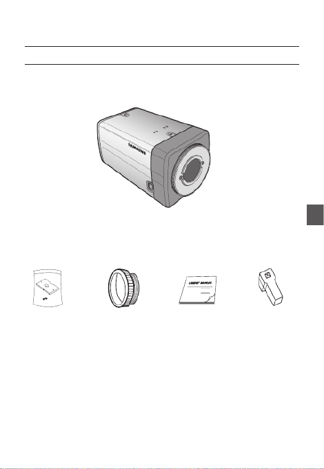
PRODUCT & ACCESSORIES
Product & Accessories❖
Accessories
•
Camera
Camera Holder(Mount) Auto Iris
Lens Connector
User’s Manual
Main Product
•
C Mount Adapter

8 – DIGITAL COLOR CAMERA
Introduction
PART NAMES AND FUNCTIONS
Side View❖
Auto Iris Lens Connector
This groove is used for screwing the mount adapter, a part of the bracket where the camera will be installed.
Auto Iris Lens Control Cable
This cable transmits the power and signals from the camera for controlling the Auto Iris Lens.
Mount Adapter Fixing Grooves
These grooves are used when fi xing screws of the mount adapter connected to the bracket when installing
the camera on it.
•
•
•
Note :
When the camera lens becomes dirty, softly clean it with a lens tissue or a cloth soaked in pure ethanol.
–
Mount Adapter
Fixing Grooves
Camera Lens
Auto Iris Lens
Connector
Auto Iris Lens
Control Cable

English – 9
ENG
Introduction
Rear Panel❖
no
r
q
p
s
<AC24/DC12V (B2333(P))>
no
q
s
<AC220V~240V(SCC-B2033P)>
p

10 – DIGITAL COLOR CAMERA
Introduction
n Input/Output Connector
This connector has input and output ports for RS-485 control signals, DAY/NIGHT switching, and alarm
output signals.
No. Function Description
1 ALARM OUT
Alarm out port for motion detection. (Open collector type)
2 GND Grounding Port.
3 GND Grounding Port.
4 SHUTTER (S0) This is a port for selecting an external high speed shutter mode.
If connected in LOW (0V), it will become ON inside.
5 SHUTTER (S1)
This is a port for selecting an external high speed shutter mode.
If connected in LOW (0V), it will become ON inside.
6 SHUTTER (S2)
This is a port for selecting an external high speed shutter mode.
If connected in LOW (0V), it will become ON inside.
7 5V OUT
Power supply port for RS-485 JIG. Use within typical DC +5V 100mA
8
DAY/NIGHT IN
This is a port for DAY&NIGHT conversion.
High(DC +3V~+5V) : DAY(COLOR) Mode,
Low(0V) : NIGHT(BW) Mode
9 RS-485 DATA-
This is a port for connection to RS-485 DATA- signal line.
10 RS-485 DATA+
This is a port for connection to RS-485 DATA+ signal line.
o SETUP Switch
This switch is used to set the function or property. When this switch is pressed for at least 2 seconds, the
MAIN MENU appears.
ef
(Left/Right)
: By pressing this switch left or right, you can move left or right on the menu or change the
displayed value.
cd
(Up/Down) :
By pressing this switch up or down, you can move up or down on the menu.
: When you press this switch in the menu, the selected function is confi rmed. To enter a submenu, press
this button.
p Power Display LED
When the power is normally connected, the red LED lights.
q Video OUT Port
This is connected to the Video Input Port of the monitor and it outputs the Video signals.
r GND
This is a grounding port.
s Power Connection Port
This is connected to the Power cable.

English – 11
ENG
Installation
CONNECTING THE AUTO IRIS LENS
CONNECTOR
Connect each uncovered shutter control cables to
the Auto Iris Lens Connector as the following
Pin
No.
DC Control
Type Video Control Type
1 Damp(-) Power (+12V)
2 Damp(+) Not applicable
3 Drive(+) Video Signal
4 Drive(-) Ground
Note :
You can switch a control type of the lens in the menu.
–
MOUNTING THE LENS
When using the CS lens
Mount the CS lens by rotating it clockwise as shown
in the picture:
When using the C lens
After mounting the C-mount adapter by rotating it
clockwise, turn the C lens clockwise until it is fi xed as
shown in the picture.
CS lens
C lens

12 – DIGITAL COLOR CAMERA
Installation
CONNECTING CABLES AND
CHECKING OPERATION
①
Connect one end of the BNC cable to the
VIDEO OUT Port on the rear of the camera.
② Connect another end of the BNC cable to the
VIDEO IN Port on the monitor.
③
Finally connect the power adapter to the
camera. You can connect 2 lines of the power
adapter to the camera using the Slot Head
screwdriver as shown in the picture.
(GND: cable with the white stripe line)
1 2
3 4
5 6 7
8
1.
ALA RAM OU
T
2. G
ND
3.
GN D
4.
S
HU T
TE R(
SO)
5.
SH U
TT E
R(S 1
)
6.
S
HUTT ER(S 2)
7.
5V O
UT
8. D
AY/N IGH T IN
Note :
Connect any power source of AC 24V and DC 12V
irrespective of polarity.
–
1
2 3
4 5
6
7 8
1. A
LA RA
M OU
T
2.
GND3
. GND
4.
SH
UTTER (SO)
5.
SHU T
TER (S
1)
6
.
SHU TTER (S2)
7. 5V OUT
8. D
AY /NI
GHT I
N
Video In Terminal of Monitor Rear
Surface
BNC cable
Video Out Terminal

English – 13
ENG
USING ICONS IN THE MENU
(EXIT)
Exits the menu setting.
Before you exits the menu setting, select SAVE to
save your settings, or select QUIT to cancel.
(RET)
Returns to the previous menu.
(HOME)
Returns to the main menu.
(SAVE)
Used to save your settings of MASK AREA,
PRIVACY ZONE and more.
Once you save your settings, they will remain
even if you select QUIT in the menu.
(DEL)
Used to deletes your settings of MASK AREA,
PRIVACY ZONE and more.
Once you delete your settings, they will not be
restored even if you select QUIT in the menu.
•
•
•
•
•
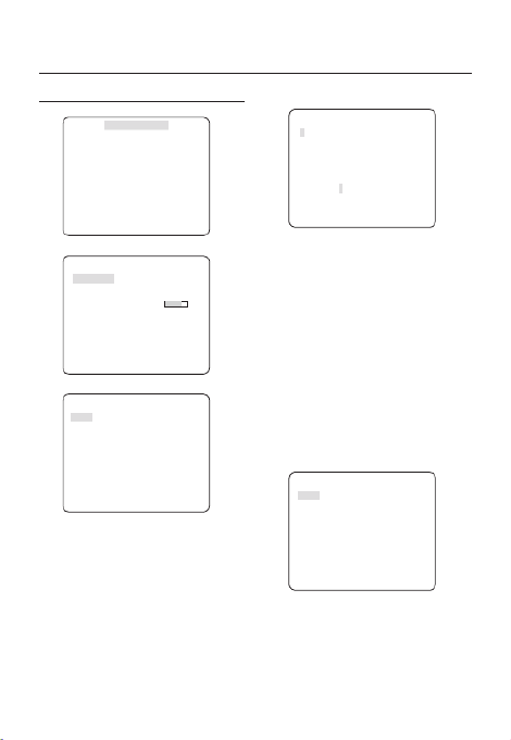
MAIN MENU
ÃÃ ÃÃMAIN MENU
PROFILE
CAMERA SET
INTELLIGENCE
PRIVACY ZONE
OTHER SET
COMMUNICATION
SYSTEM INFO
LANGUAGE
PROFILE
You can set a mode according to the camera
installation conditions.
CAMERA SET
Confi gure Camera related functions and data.
INTELLIGENCE
You can confi gure the settings of motion
detection, tracking and more.
PRIVACY ZONE
You can confi gure the privacy related settings.
OTHER SET
You can confi gure for Factory Defaults, and more.
COMMUNICATION
Confi gures the settings regarding the RS-485
communication.
SYSTEM INFO.
Displays the system information including the
camera version and communication settings.
LANGUAGE
Select a preferred one from the supported
languages.
•
•
•
•
•
•
•
•
How to use OSD Menu

14 – DIGITAL COLOR CAMERA
How to use OSD Menu
PROFILE
e
PROFILE
f
Ã
STANDARD
ITS
BACKLIGHT
DAY/NIGHT
GAMING
CUSTOM
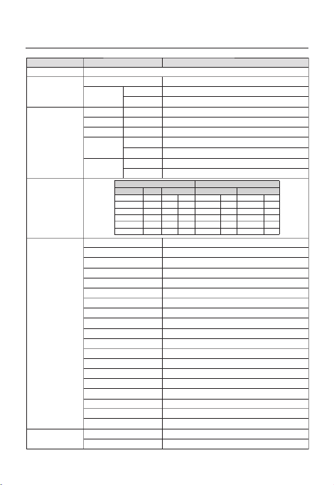
In the menu, you can confi gure the following camera settings at once.PROFILE
CAMERA SET Menu
STANDARD ITS BACKLIGHT DAY/NIGHT GAMING
Previous
Menu Sub-menus
IRIS ALC ALC ALC ALC ALC
ALC - - - - -
LENS DC DC DC DC DC
LEVEL 0 0 0 0 0
BACKLIGHT OFF OFF BLC OFF OFF
MOTION (F.FAST)--- (F.FAST)--- NORM (F.FAST)--- SLOW
DNR MID MID MID MID MID
SHUTTER OFF AUTO1/250 OFF OFF OFF
SENS-UP AUTOx4 AUTOx2 AUTOx4 AUTOx4 AUTOx4
XDR MID MID MID MID MID
DAY/
NIGHT AUTO AUTO DAY AUTO DAY
NIGHT - - - - -
BURST OFF ON OFF OFF OFF
EXT - - - - -
BURST OFF ON OFF OFF OFF

English – 15
ENG
How to use OSD Menu
CAMERA SET Menu
STANDARD ITS BACKLIGHT DAY/NIGHT GAMING
Previous
Menu Sub-menus
WHITE
BAL DAY DAY/NIGHT DAY DAY/NIGHT DAY
DAY - - - - -
MODE ATW2 ATW1 ATW1 ATW1 ATW1
RED 0 0 0 0 0
BLUE 0 0 0 0 0
NIGHT - - - - -
BRIGHTNESS
User setting
allowed MID User setting
allowed MID User setting
allowed
MODE OFF ATW2 OFF ATW2 OFF
RED User setting
allowed 0User setting
allowed 0User setting
allowed
BLUE User setting
allowed 0User setting
allowed 0User setting
allowed
DETAIL 2 2 2 2 2
ITS
It will be set automatically so you can easily check the traffi c conditions.
BACKLIGHT
It will be set automatically so you can distinguish the object from the background in a severe backlighting scene.
DAY/NIGHT
It will be set automatically so it optimizes to the day or night conditions, respectively.
GAMING
It will be set automatically to help you take a picture in a regular indoor lighting condition.
❖
❖
❖
❖
16 – DIGITAL COLOR CAMERA
How to use OSD Menu
CAMERA SETUP
e fCAMERA SET
CAMERA ID OFF
IRIS ALC
MOTION (F.FAST)---
DNR MID
SHUTTER OFF
SENS-UP AUTO X4
FLICKERLESS (OFF)---
XDR MID
d
c
DAY/NIGHT AUTO
WHITE BAL
DIGITAL ZOOM
OFF
DETAIL [2]
V-SYNC INT
AGC COLOR SUP
LOW
REVERSE OFF
POSI/NEGA +
PIP OFF
d
c
DIS OFF
Setup the general functions of zoom camera module.
Use the
cdef
switch to select a menu item.
CAMERA ID [OFF, ON]
CAMERA ID
ABCDEFGHIJKLMNOPQRSTUVWXYZ0
123456789 :?-+*()/
SP
ffee
SP LOCATION
CAMERA-1..................
...........................
The CAMERA ID menu is used for you to assign
a unique name to a camera. If you press the
SETUP switch with the menu CAMERA ID
selected, you will see the appropriate screen.
You can enter up to 54 alphanumeric or
special characters for the . Select CAMERA ID
LOCATION SETUP and press the switch to
move the display position of the CAMERA ID.
IRIS [ALC, ELC]
The IRIS menu is used if you want to adjust the
intensity of radiation incoming to the camera.
ALC (Automatic Light Control)
① If you press the SETUP switch with an ALC-
based sub menu selected, you will see the
appropriate screen.
ALC
LENS DC
LEVEL [00]----I----
BACKLIGHT OFF
The menu is used if you select a type of LENS
the AI lens.
For normal operation, you must select for a DC
DC-type lens, and select for a VIDEO-VIDEO
type lens.
❖
❖
•

English – 17
ENG
How to use OSD Menu
The menu is used to adjust the LEVEL
overall brightness, where “+” will increase the
brightness and “–” will decrease it.
② If you set the BACKLIGHT option to BLC,
you will see a menu where you can set the
BLC area.
you can set the desired zone by de ning BLC
the size and location.
ALC
LENS DC
LEVEL [00]----I----
BACKLIGHT BLC
AREA USER
<SIZE>
<LOCATION>
If you use an ordinary camera in a scene
with an intensive backlight, the object will be
displayed dark on the monitor affected by the
backlight. To solve this problem, you can use
the BLC(Back Light Compensation) function
to improve the sharpness of the image in
such a high contrast scene.
ELC (Electronic Light Control)
①
If you press the switch when the SETUP ELC
submenu is selected, the corresponding screen
appears. You can make the (Electronic Light ELC
Control) function active or not.
ELC
LEVEL [00]----I----
BACKLIGHT OFF
•
② In similar to setting, you can specify the ALC
BLC area.
ELC
LEVEL [00]----I----
BACKLIGHT BLC
AREA USER
<SIZE>
<LOCATION>
AGC
[OFF, VERY LOW, LOW, MID, HIGH, VERY
HIGH, USER, FIX]
The AGC (Auto Gain Control) menu is used to
set the AGC level of the camera. When the AGC
is active, the camera automatically increases the
sensitivity by amplifying the Video signal when
the strength of the signal falls below the normal
value.
If or mode is selected in the OFF FIX SENS-UP
menu, you can specify the level.AGC
If you press the switch with a SETUP USER
sub menu selected, you will see the appropriate
screen.
AGC USER
LEVEL [16]
In USER mode, you can break down the level in
16 steps from to to your VERY LOW VERY HIGH
preference.
❖

18 – DIGITAL COLOR CAMERA
How to use OSD Menu
AGC FIX
LEVEL [01]
If you press the switch with a sub SETUP FIX
menu selected, you will see the appropriate screen.
As a xed value of the gain is used in AGC FIX
mode, you can select one of the 16 detailed levels
from to before xing it.VERY LOW VERY HIGH
Note :
If the menu of the is set to DAY/NIGHT CAMERA SET
AUTO, the AGC menu will be deactivated.
If is set to , the mode will be FLICKERLESS ON AGC FIX
disabled.
MOTION
[S.SLOW, SLOW, NORM, FAST, F.FAST]
The menu is used to adjust the strength MOTION
of the level for a control of the camera motion. AGC
This is available only if the menu is set SENS-UP
to AUTO.
You can select one from , , S.SLOW SLOW NORM,
FAST F.FAST AGC and for the level.
If you monitor a fast moving object in a low contrast
scene, select while select for a F.FAST S.SLOW
hardly moving object in the same lighting condition.
Note :
If the menu of the is set to DAY/NIGHT CAMERA SET
AUTO, the MOTION menu will be deactivated.
DNR
[OFF,LOW,MID,HIGH, USER(1~16)]
You can con gure the DNR (Digital Noise
Reduction) related settings.
Reduces the noise on the screen.
This is especially useful for a severely distorted screen.
You can set the level if you set DNR USER to .
–
–
❖
–
❖
SHUTTER
[OFF, AUTO 1/100(PAL:1/120), AUTO 1/250,
AUTO 1/500, AUTO 1/1000, AUTO 1/2000, AUTO
1/4000, AUTO 1/10K , 1/100(PAL:1/120), 1/250,
1/500, 1/1000, 1/2000, 1/4000, 1/10K , EXT]
The SHUTTER menu is used to set the xed
high-speed electronic shutter, auto high speed
electronic shutter and external high speed
electronic shutter(EXT).
You can select one of 7 options from 1/100(PAL:1/120)
to 1/10K for the xed high speed electronic shutter,
which is mostly used for imaging a fast moving object.
The auto high speed electronic shutter operates
as the xed high speed shutter in a high contrast
scene but automatically focuses the target if the
iris opens fully in a low contrast scene like in ELC
mode. When it gets brighter back, the mode will
switch to the xed high speed electronic shutter
mode.
However, the auto high speed shutter operates
properly only in a camera featuring a DC or VIDEO
lens.
In external high speed electronic shutter (EXT)
mode, you can select one of 8 modes from OFF
through 1/100(PAL:1/120) to 1/10K for the high
speed electronic shutter. It works as the high
speed electronic shutter. You can select an
option using SHUTTER(S0), SHUTTER(S1) and
SHUTTER(S2) on the rear.
Connect each of the terminals to GND.
See the below table for the operation.
SHUTTER(S0) SHUTTER(S1) SHUTTER(S2)
OFF
(NTSC: 1/60,
PAL:1/50)
OFF OFF OFF
1/100
(PAL:1/120)
ON OFF OFF
1/250 OFF ON OFF
1/500 ON ON OFF
1/1000 OFF OFF ON
❖

English – 19
ENG
How to use OSD Menu
1/2000 ON OFF ON
1/4000 OFF ON ON
1/10K ON ON ON
Note :
If mode is set to , the menu will be IRIS ELC SHUTTER
deactivated as you adjust the brightness using the
electronic shutter.
If the function is set to , only items of SENS-UP AUTO
OFF and are available in the menu.AUTO SHUTTER
If the mode is set to , the menu SENS-UP FIX SHUTTER
will be deactivated.
If the function is set to , the menu FLICKERLESS ON SHUTTER
will be deactivated.
SENS-UP
[OFF, AUTO X2, AUTO X4, AUTO X6, AUTO
X8, AUTO X12, AUTO X16, AUTO X24, AUTO
X32, AUTO X48, AUTO X64, AUTO X96, AUTO
X128, AUTO X256, AUTO X512, FIX X2, FIX
X4, FIX X6, FIX X8, FIX X12, FIX X16, FIX X24,
FIX X32, FIX X48, FIX X64, FIX X96, FIX X128,
FIX X256, FIX X512]
Automatically detects the ambient level of
darkness in the dark or low contrast scene to
extend the accumulated time, keeping the image
bright and sharp; It can be also used as FIX
mode.
Note :
If the option is set to xed electronic shutter or SHUTTER
EXT SENS-UP mode, the menu will be deactivated.
If is set to , the mode of the FLICKERLESS ON FIX SENS-
UP menu will be disabled.
If the menu is set to , the electronic shutter will IRIS ELC
control the brightness so the function can not SENS-UP
be set to mode, but to or mode.FIX OFF AUTO
If the menu is set to , the SHUTTER AUTO SENS-UP
menu can be set to either or mode.OFF AUTO
–
–
–
–
❖
–
–
–
–
FLICKERLESS [OFF, ON]
If set to , the shutter speed will be xed to ON
1/100(PAL:1/120) second. This will prevent possible screen
distortion due to a mismatch between the vertical sync
frequency and the blinking frequency of the lighting.
Note :
If the function is set to , the Flickerless menu will IRIS ELC
be deactivated. If the menu is set to , SHUTTER AUTO FIX
or mode, the Flickerless menu will be deactivated.EXT
If the function is set to mode, the Flickerless SENS-UP FIX
menu will be deactivated.
If is set to mode, the function will AGC FIX FLICKERLESS
be disabled.
XDR (eXtended Dynamic Range)
[OFF, LOW, MID, HIGH]
Actively controls the gamma compensation in the
way it operates the ambient luminance contrast
in a certain pixel unit to determine the optimal
visibility.
Select one from and OFF LOW MID, , HIGH.
Closing to HIGH will increase the compensation
level.
DAY/NIGHT
[DAY,NIGHT,AUTO,EXT]
DAY
If set to DAY, it will be xed to mode DAY
regardless of the ambient conditions.
NIGHT
If set to , it will be xed to Black-and-White NIGHT
mode regardless of the ambient conditions.
If you press the switch with a sub SETUP NIGHT
menu selected, you will see a menu where you can
set Burst to OFF/ON.
If is set to , the Burst signal will output BURST ON
together with the black-and-white composite video
signal. If is set to , the Burst signal does BURST OFF
not output.
You can set the option to , or BURST OFF/ON
select to output the Burst signal in NIGHT mode.
❖
–
–
–
❖
❖
•
•

20 – DIGITAL COLOR CAMERA
How to use OSD Menu
AUTO
The camera will automatically switch between
DAY and NIGHT mode, according to the lighting
condition.
If you press the switch with an SETUP AUTO-
based sub menu selected, you will see the
appropriate screen.
AUTO
BURST OFF
DAY NIGHTÆ
BRIGHTNESS MID
DWELL TIME 2S
NIGHT DAYÆ
BRIGHTNESS MID
DWELL TIME 5S
MASK AREA 1 2
You can set the option to BURST OFF/ON, or
select to output the Burst signal in NIGHT mode.
You can select from and LOW MID, HIGH for
the brightness of , which is a DAY NIGHTÆ
brightness level in switching from the color lter
to Black-and-White. Closing to LOW HIGH from
will switch the lter in a low contrast scene.
The of is a time DWELL TIME DAY NIGHTÆ
required to determine the need for switching the
lter.
You can select from and LOW MID, HIGH for
the brightness of , which is a NIGHT DAYÆ
brightness level in switching from the Black-and-
White lter to color. Closing to from LOW HIGH
will switch the lter in a low contrast scene.
The of is a time DWELL TIME NIGHT DAYÆ
required to determine the need for switching the
lter.
The MASK menu is used to prevent a lter
switch error or inability of determining the switch
in existence of a high spot light source at night.
If you press the SETUP switch in item 1 or 2 of
the MASK menu, you will see a menu where you
can specify an area to mask.
•
MASK AREA
<SIZE>
<LOCATION>
You can specify Mask 1 and 2 simultaneously.
The mask is used only for determining the lter
switch and any excessive bright area at night will
be masked.
Note :
If is set to , the function will BACKLIGHT BLC MASK AREA
be deactivated.
EXT
This enables an auto switch between and DAY
NIGHT mode using the interface with the external
sensor.
WHITE BAL [DAY/NIGHT]
If you want to adjust the color scheme, use the
WHITE BALANCE function.
DAY
In mode, you can set the color values of DAY
RED BLUE and . The screen will be displayed in
colors according to your settings.
WHITE BAL
DAY/NIGHT DAY
MODE AWC
RED [00]----I----
BLUE [00]----I----
R-GAIN [0248]
B-GAIN [0247]
Note :
You can set the values of and only in R-GAIN B-GAIN
AWC mode.
–
•
❖
•
–

English – 21
ENG
How to use OSD Menu
NIGHT
Use the mode if you want to set the white NIGHT
balance differently according to the ambient
luminance.
If the mode is set to , the white NIGHT OFF
balance will always operate as set in mode; DAY
if not to , the camera will switch to as set in OFF
DAY/NIGHT mode according to the brightness.
In mode, you can set the values of NIGHT RED,
BLUE BRIGHTNESS and . The screen will be
displayed in colors according to your settings.
WHITE BAL
DAY/NIGHT NIGHT
BRIGHTNESS MID
MODE AWC
RED [00]----I----
BLUE [00]----I----
R-GAIN [0248]
B-GAIN [0247]
Note :
You can set the values of and only in R-GAIN B-GAIN
AWC mode.
If is set to or , you can not access the AGC OFF FIX
NIGHT menu.
For adjusting the white balance, the following
5 modes are provided:
ATW1(Auto Tracing White Balance mode
1): The camera can automatically adjust the
color temperature in real time, according to
the ambient conditions. The color temperature
ranges from approx. 2500K to 9300K.
ATW2: The color temperature ranges from
approx. 2,000K to 10,000K.
AWC ( Auto White Balance Control): If you
press the switch in the appropriate item SETUP
position, Auto White Balance will perform once.
3200K : Set color temperature to 3200K
5600K : Set color temperature to 5600K
•
–
–
–
•
•
•
•
•
RED : Adjusts the strength of the red color.
BLUE : Adjusts the strength of the blue color.
R-GAIN B-GAIN/ : Enables you to set the current
color temperature manually.
BRIGHTNESS : Select a brightness level in
switching from setting in mode to setting in DAY
NIGHT mode.
DIGITAL ZOOM [ON/OFF]
You can set the digital zoom factor and position.
If you press the SETUP switch with the DIGITAL
ZOOM ON function set to , you will see the
appropriate screen.
When the zoom factor and position are de ned,
the digital zoom function will operate.
DIGITAL ZOOM
RATIO [X1.0]
< LOCATION >
-
LOCATION SETUP : If you press the switch in the
condition where the image is enlarged as much as the
ratio setting, you can watch an invisible area of the
effective screen as well using the
cdef
switch.
Note :
If the digital zoom factor is set to larger than 1x, the FENCE
function will be deactivated.
The function enlarges the pixel itself, which can DIGITAL ZOOM
cause deterioration of the quality.
DETAIL [0~3]
Controls the horizontal or vertical distinction.
–
–
–
–
❖
–
❖

22 – DIGITAL COLOR CAMERA
How to use OSD Menu
V-SYNC [INT, LINE]
Select the vertical sync mode for INT LINE or .
If you select , the camera will use the internal INT
synchronization.
If selecting LINE, the camera will use the external
power source frequency for the synchronization.
You can adjust the LL-PHASE.
Note :
Use of DC 12V will x to , which can not be V-SYNC INT
changed.
AGC COLOR SUP [LOW , MID, HIGH]
Adjust the color scheme according to the AGC
value.
REVERSE [OFF, H, V, H/V]
Mirrors video signals horizontally, vertically, or
both.
POSI/NEGA [+, -]
Output as it is or mirror the video brightness
signal.
PIP [OFF, ON]
Displays a sub image together with the main
image on the same screen using the Picture In
Picture function.
Note :
If more than one privacy zone is set and the PRIVACY
SET PIP is set to ON, the function will be deactivated.
If the function is set to mode, the INTELLIGENCE FENCE
PIP menu will be deactivated.
DIS [OFF, ON]
Digital Image Stabilization will set the anti-shake
compensation.
Note :
If you set to , the compensation area will be DIS ON
enlarged as set in the digital zoom factor.
If you set the digital zoom factor to greater than the
enlarged zoom factor for the compensation, the DIS
function will be deactivated.
❖
–
❖
❖
❖
❖
–
–
❖
–
INTELLIGENCE
e fINTELLIGENCE
MOTION OFF
ADVANCED OFF
MASK AREA
1 2 3 4
DISPLAY ON
SENSITIVITY [4]
RESOLUTION [5]
ALARM OUT
You can set the motion detection and tracking in the
INTELLIGENCE menu.
MOTION
[OFF,TRACKING,DETECTION]
TRACKING
Detects and tracks a moving object.
DETECTION
Detects a moving object.
Note :
If it is set to , you can not set such functions as DETECTION
FIXED/MOVED FENCE ADVANCED and in the menu.
ADVANCED
[OFF, FIXED/MOVED, FENCE]
Detects a motion of an object and displays an
image of any moving object before tracking the
moving route.
FENCE
This is to detect if a moving object passes
through the speci ed LINE AREA or .
In a condition where a moving object is detected
in an analysis of the previous and current frames
whose movement overlaps a certain area, the
system displays “PASS” if the object’s center line
passes through the line while it displays “ENTER”
or “EXIT” if the center point passes through the
area.
❖
•
•
–
❖
•

English – 23
ENG
How to use OSD Menu
FENCE
LINE OFF
AREA OFF
You can set the position and detection direction of the
LINE AREA, and the size and position of the .
- How to set the line
LINE
PIXEL LEVEL [4]
<POINT>
DIRECTION §¨
① If you press the switch with the SETUP LINE
option set to , you can specify the position ON
and detection direction of the line.
② If you change the PIXEL LEVEL for setting
the position, specify the pixel that moves by a
single pressure of the
cdef
switch.
③
In , you can specify the rst position of <POINT>
the line by pressing the switch once, and SETUP
the second position by pressing the switch again.
Use the
cdef
switch to specify the
position.
Set each position of the two points and press the
SETUP switch to complete the positioning.
④
If you change the , you can specify DIRECTION
the detection direction. The detection direction
based on the de ned two points will be
displayed on the screen.
- How to set the area
AREA
PIXEL LEVEL [4]
<SIZE>
<LOCATION>
① If you press the SETUP switch with the AREA
option set to ON, you can specify the position
and size of the area.
② If you change the PIXEL LEVEL for setting
the position, specify the pixel that moves by a
single pressure of the
cdef
switch.
③
In , press the switch and use <SIZE> SETUP
the
cdef
switch to adjust the size.
Press the switch again to complete the SETUP
sizing.
④
In <LOCATION>, press the SETUP switch and
use the
cdef
switch to specify the position.
Press the switch again to complete SETUP
the positioning.
Note :
If you set the of the to , 12 will LINE FENCE ON PRIVACY
not be available.
Functions of , , and (if the FENCE PIP DIS DIGITAL ZOOM
digital zoom factor is set to larger than 1x) can not be
used simultaneously.
In the boundary of the de ned and LINE, a AREA FENCE
detection error may occur if two or more moving objects
overlap with each other or one object separates in
multiple directions.
FIXED/MOVED
If an object on the screen suddenly disappears or
an object comes out of nowhere and stays for a
certain time, the area will be displayed.
A detection ( ) error may occur if :FIXED/MOVED
- multiple motions occur continuously in random
directions
- a xed object moves in one position continuously
- a second object screens the rst moving object
–
–
•

24 – DIGITAL COLOR CAMERA
How to use OSD Menu
MASK AREA [1~4]
Specify a detection exception area to mask.
Select a mask number and specify the size and
position.
MASK AREA
<SIZE>
<LOCATION>
DISPLAY [ON, OFF]
With the , a motion or DISPLAY ON option set to
a set ADVANCED function will be displayed on
the screen, if detected.
SENSITIVITY [1~7]
Set the sensitivity of the motion detection.
RESOLUTION [1~5]
If setting it to high, the camera can detect even a
trivial movement of the target.
ALARM OUT
If you set a desired menu item to , the camera ON
will sound an alert if it detect the appropriate
motion.
ALARM OUT
MOTION ON
FIXED/MOVED ON
FENCE
LINE ON
AREA
ENTER ON
EXIT ON
❖
❖
❖
❖
❖
PRIVACY ZONE SETUP
e fPRIVACY ZONE
1 2 3 4 5 6
7 8 9
10
11
12
PRIVACY SET ON
STYLE
MOSAIC1
The function will protect your privacy by PRIVACY
screening the privacy area that you have specifi ed
during monitoring. You can specify up to 12 privacy
zones.
If you set the to , your PRIVACY SET ON PRIVACY
ZONE settings will be applied.
You can change the style to adjust the mosaic size
and color of the PRIVACY ZONE.
e fPRIVACY ZONE
1 2 3 4 5 6
7 8 9
10
11
12
PRIVACY SET ON
STYLE COLOR
Y-LEVEL [128]
RED [128]
BLUE [128]
Use the
cdef
switch to select one from
PRIVACY 1 through 12.
Select one from 1~12 and press the PRIVACY
SETUP switch to confi rm your setting. You can
specify a pixel that moves as you change the PIXEL
LEVEL to set the position.
PRIVACY ZONE SET1
PIXEL LEVEL [4]
<POINT>
<POSITION>

26 – DIGITAL COLOR CAMERA
How to use OSD Menu
COMMUNICATION
e fCOMMUNICATION
RS-485
PROTOCOL
SAMSUNG
BAUD RATE 9600
ADDRESS 0
The menu is used to confi gure COMMUNICATION
the settings regarding RS-485 communications.
Use the rear panel of the camera to connect to
RS-485.
[Camera I/O Connector]
Use the
cdef
switch to specify the protocol,
baud rate and address (0~255) for communications.
PROTOCOL
Select a communication protocol.
BAUD RATE
Select a baud rate.
Note :
The baud rate differs, depending on the specifi ed
protocol.
ADDRESS
[0~255]
You must specify a unique address for each
camera in the same RS-485 network.
To control a specifi c camera, you must match the
address of the camera with that of the DVR or the
controller.
❖
❖
–
❖
SYSTEM INFORMATION
e fSYSTEM INFO
TYPE 3_BOX_NOR_N
PROTOCOL
SAMSUNG
ADDRESS 1
COMM. TYPE RS-485,HALF
BAUD RATE
9600
SERIAL NO.
000000000000000
CAMERA VER. 0.50_090101
EEPROM VER. 0.50_090101
You can view the system information including the
protocol, address, baud rate, serial number, camera
version, and EEP version.
LANGUAGE
e fLANGUAGE
ÃENGLISH
P CCKNУ Й
POLSKI
ČESKY
TÜRKÇE
The camera supports 5 different languages.
Select a preferred language.

English – 27
ENG
How to use OSD Menu
Initial Confi guration Table
Camera Confi guration
•
CAMERA ID OFF
IRIS ALC
AGC VERY HIGH
MOTION (F.FAST)
DNR MID
SHUTTER OFF
SENS-UP
AUTO x4
FLICKERLESS (OFF)
XDR MID
DAY/NIGHT AUTO
DIGITAL ZOOM OFF
DETAIL [2]
AGC COLOR SUP MID
REVERSE OFF
POSI/NEGA +
PIP OFF
DIS OFF
V-SYNC INT
❖

28 – DIGITAL COLOR CAMERA
Speci cations
SPECIFICATIONS
Items Sub-items SCC-B2333N
Camera Type CCTV Camera (DAY/NIGHT)
Image
Device 1/3” Super-HAD IT CCD
Pixels Total 811 x 508
Effective 768 x 494
Scanning
System Interlace
Scanning Line 525 lines
Frame 30frame/1sec
Horizontal
Frequency
Internal Mode 15,734 Hz
Line-lock Mode 15,750 Hz
Vertical
Frequency
Internal Mode 59.94 Hz
Line-lock Mode 60 Hz
Min. Scene
Illumination
Condition Min. Scene illumination
Sens-up F No. Level DAY NIGHT
OFF 1.2 50 IRE 0.4 Lux 0.04 Lux
OFF 1.2 30 IRE 0.24 Lux 0.024 Lux
OFF 1.2 15 IRE 0.12 Lux 0.012 Lux
512 times 1.2 50 IRE 0.0008 Lux 0.00008 Lux
512 times 1.2 30 IRE 0.00047 Lux 0.000047 Lux
512 times 1.2 15 IRE 0.00023 Lux 0.000023 Lux
Functions
Number of Privacy Zone 12 (Polygonal Method)
Day/Night DAY/NIGHT/AUTO/EXT
Motion Detection OFF/Tracking/Detection
eXtended Dynamic Range(XDR) Off/On (Level Setting)
D-Zoom x1 ~ p28-x16 (x0.1 STEP)
PIP Off/On
High Speed Shutter 1/60 ~ 1/10Ksec (OSD/External Control)
Flickerless Off/On
Sens-Up x2 ~ x512
BLC Off/On (Area Setting)
AGC Off/On (Max.Level Setting)
ELC Off/On ( ~ 1/200K sec)
Line Lock Off/On (Phase Control)
Camera ID Off/On (Max.54ea/2Line)
White Balance ATW1/ATW2/AWC/3200K/5600K
Digital Noise Reduction(DNR) Off/On (Adaptive 3D+2D)
Digital Image Stabilization(DIS)
Off/On
Intelligent Video Fixed/Moved, Fence
Etc. Function Detail, Reverse(H/V), Posi/Nega

English – 29
ENG
Speci cations
Items Sub-items SCC-B2333N
Resolution Horizontal 600 TV Lines
Vertical 350 TV Lines
Video Output - VBS 1.0Vp-p, 75 Ω
S/N Ratio S/N Ratio Approx. 52dB
Lens Lens Drive Type MANUAL/AI(VIDEO/DC)
Mount Type CS/C
Alarm Input N/A
Output 1 Output
Remote
Control
Coaxitron (Data On Coax cable) Yes (with SCX-RD100)
RS-485 Yes (Multi Protocol, 8ea)
Environmental
Conditions
Operating Temperature -10˚C ~ +50˚C
Humidity Less than 90%
Power
Power Requirement AC24V ± 10%(60Hz ± 0.3Hz)
DC12V ± 10%
Power Consumption
(With DC Lens)
In normal operation : 2.3W
In switching the DAY/NIGHT lter : 2.8W
LED Indicator Yes
Physical
Speci cation
Dimensions
(WxHxD)
Net 64(W) x 58(H) x 109.2(D) mm
Package 173(W) x 99(H) x 115(D) mm
Weight Net 305g
Package 530g
Color Body Silver
30 – DIGITAL COLOR CAMERA
Speci cations
Items Sub-items SCC-B2333P / SCC-B2033P
Camera Type CCTV Camera (DAY/NIGHT)
Image
Device 1/3” Super-HAD IT CCD
Pixels Total 795 x 596
Effective 752 x 582
Scanning
System Interlace
Scanning Line 625 lines
Frame 25frame/1sec
Horizontal
Frequency
Internal Mode 15,625 Hz
Line-lock Mode 15,625 Hz
Vertical
Frequency
Internal Mode 50 Hz
Line-lock Mode 50 Hz
Min. Scene
Illumination
Condition Min. Scene illumination
Sens-up F No. Level DAY NIGHT
OFF 1.2 50 IRE 0.4 Lux 0.04 Lux
OFF 1.2 30 IRE 0.24 Lux 0.024 Lux
OFF 1.2 15 IRE 0.12 Lux 0.012 Lux
512 times 1.2 50 IRE 0.0008 Lux 0.00008 Lux
512 times 1.2 30 IRE 0.00047 Lux 0.000047 Lux
512 times 1.2 15 IRE 0.00023 Lux 0.000023 Lux
Functions
Number of Privacy Zone 12 (Polygonal Method)
Day/Night DAY/NIGHT/AUTO/EXT
Motion Detection OFF/Tracking/Detection
eXtended Dynamic Range(XDR) Off/On (Level Setting)
D-Zoom Max. x16
PIP Off/On
High Speed Shutter 1/50 ~ 1/10Ksec (OSD/External Control)
Flickerless Off/On
Sens-Up x2 ~ x512
BLC Off/On (Area Setting)
AGC Off/On (Max.Level Setting)
ELC Off/On ( ~ 1/200K sec)
Line Lock Off/On (Phase Control)
Camera ID Off/On (Max.54ea/2Line)
White Balance ATW1/ATW2/AWC/3200K/5600K
Digital Noise Reduction(DNR) Off/On (Adaptive 3D+2D)
Digital Image Stabilization(DIS)
Off/On
Intelligent Video Fixed/Moved, Fence
Etc. Function Detail, Reverse(H/V), Posi/Nega
Resolution Horizontal 600 TV Lines
Vertical 350 TV Lines

English – 31
ENG
Speci cations
Items Sub-items SCC-B2333P / SCC-B2033P
Video Output - VBS 1.0Vp-p, 75 Ω
S/N Ratio S/N Ratio Approx. 52dB
Lens Lens Drive Type MANUAL/AI(VIDEO/DC)
Mount Type CS/C
Alarm Input N/A
Output 1 Output
Remote
Control
Coaxitron (Data On Coax cable) Yes (with SCX-RD100)
RS-485 Yes (Multi Protocol, 8ea)
Environmental
Conditions
Operating Temperature -10˚C ~ +50˚C
Humidity Less than 90%
Power
Power Requirement
SCC-B2333P : AC24V ± 10%(50Hz±0.3Hz)
DC12V ± 10%
SCC-B2033P : AC220V ± 10%(50Hz±0.3Hz)
Power Consumption
(With DC Lens)
In Normal operation :
SCC-B2333P : 2.3W
SCC-B2033P : 2.9W
In switching the DAY/NIGHT lter :
SCC-B2333P :2.8W
SCC-B2033P : 3.4W
LED Indicator Yes
Physical
Speci cation
Dimensions
(WxHxD)
Net SCC-B2333P : 64(W) x 58(H) x 109.2(D) mm
SCC-B2033P : 64(W) x 58(H) x 129.2(D) mm
Package 173(W) x 99(H) x 115(D) mm
Weight
Net SCC-B2333P : Approx. 305g
SCC-B2033P : Approx. 395g
Package SCC-B2333P : Approx. 530g
SCC-B2033P : Approx. 620g
Color Body Silver

Correct Disposal of This Product (Waste Electrical & Electronic Equipment)
(Applicable in the European Union and other European countries with separate collection systems)
This marking on the product, accessories or literature indicates that the product and its electronic accessories
(e.g. charger, headset, USB cable) should not be disposed of with other household waste at the end of their
working life. To prevent possible harm to the environment or human health from uncontrolled waste disposal,
please separate these items from other types of waste and recycle them responsibly to promote the sustainable
reuse of material resources.
Household users should contact either the retailer where they purchased this product, or their local government
office, for details of where and how they can take these items for environmentally safe recycling.
Business users should contact their supplier and check the terms and conditions of the purchase contract.
This product and its electronic accessories should not be mixed with other commercial wastes for disposal.

ЦВЕТНАЯ ЦИФРОВАЯ
КАМЕРА
руководство пользователя
SCC-B2333(P)
SCC-B2033P
удивительные возможности
Благодарим Вас за приобретение данного продукта компании Samsung.
Для получения более полного обслуживания
зарегистрируйте свое устройство по адресу:
www.samsungsecurity.com
RUS

2 – ЦВЕТНАЯ ЦИФРОВАЯ КАМЕРА
Меры предосторожности
ВНИМАНИЕ
ОПАСНОСТЬ ПОРАЖЕНИЯ ЭЛЕКТРИЧЕСКИМ
ТОКОМ! НЕ ОТКРЫВАТЬ!
ВНИМАНИЕ: ВО ИЗБЕЖАНИЕ ПОРАЖЕНИЯ ЭЛЕКТРИЧЕСКИМ ТОКОМ НЕ ОТКРЫВАЙТЕ КРЫШ
УСТРОЙСТВА. ВНУТРИ ОТСУТСТВУЮТ ДЕТАЛИ, ОБСЛУЖИВАНИЕ КОТОРЫХ МОЖЕ
ОБСЛУЖИВАНИЕ ДОЛЖНО ВЫПОЛНЯТЬСЯ КВАЛИФИЦИРОВАННЫМИ СПЕЦИАЛИС
Этот символ обозначает, что внутри устройства имеется опасное напряжение,
которое может привести к поражению электрическим током.
Этот символ указывает, что в документации на изделие имеется важная инструкция
по его использованию или обслуживанию.
ПРЕДУПРЕЖДЕНИЕ
Во избежание повреждений, следствием которых может быть пожар или поражение
электрическим током, не допускайте попадания данного изделия под дождь или в условия
высокой влажности.
ПРЕДУПРЕЖДЕНИЕ
Пользуйтесь только стандартным блоком питания, который указан в листе спецификаций.
Использование любого другого блока питания может привести к пожару, поражению
электрическим током или к повреждению изделия.
Неправильное подключение блока питания или замена батареи может привести к взрыву,
пожару, поражению электрическим током или к повреждению изделия.
Не подключайте несколько видеокамер к одному блоку питания. Превышение нагрузочной
способности блока питания может привести к его перегреву или к пожару.
Надежно вставьте вилку сетевого шнура в розетку сети переменного тока. Ненадежное
подключение может привести к пожару.
При установке видеокамеры закрепите ее прочно и надежно. Падение видеокамеры может
привести к травме.
Не кладите сверху на видеокамеру токопроводящие предметы (например, отвертки,
монеты и другие металлические предметы) и не ставьте на нее наполненные водой сосуды.
Невыполнение этих требований может привести к пожару, поражению электрическим
током или к травмам в результате падения этих предметов.
Не устанавливайте изделие во влажных, запыленных или покрытых копотью помещениях.
Невыполнение этого требования может привести к пожару или к поражению электрическим
током.
Если вы почувствуете необычный запах или обнаружите дым, выходящий из изделия,
прекратите эксплуатацию. В этом случае следует немедленно отсоединить изделие от
источника питания и связаться с сервисным центром. Продолжение эксплуатации изделия в
таком состоянии может привести к пожару или к поражению электрическим током.
•
1.
2.
3.
4.
5.
6.
7.
8.

Pyccкий – 3
RUS
Меры предосторожности
При обнаружении неисправности в изделии свяжитесь с ближайшим сервисным центром.
Никогда не разбирайте данное изделие и не вносите изменений в его конструкцию.
(Компания SAMSUNG не несет ответственности за проблемы, возникшие в результате
внесения изменений в конструкцию изделия или попыток самостоятельно выполнить
ремонт изделия).
При чистке изделия не разбрызгивайте на него воду. Это может привести к пожару или к
поражению электрическим током
ВНИМАНИЕ
Не роняйте на изделие никакие предметы и не ударяйте по нему. Не устанавливайте
изделие в местах с сильной вибрацией или вблизи источников магнитного поля.
Не устанавливайте изделие в помещениях с высокой температурой (выше 50°С),
пониженной температурой (ниже -10°С) или высокой влажностью. Это может привести к
возгоранию или поражению электрическим током.
Если вы хотите переместить ранее установленное изделие на новое место, отключите перед
этим питание изделия.
Во время грозы отсоедините шнур питания видеокамеры от розетки сети переменного тока.
Невыполнение этого требования может привести к пожару или к повреждению изделия.
Устанавливайте изделие так, чтобы на него не падал прямой солнечный свет и чтобы рядом
не было источников, излучающих тепло. Это может привести к пожару.
Изделие должно устанавливаться в помещении с хорошей вентиляцией.
Избегайте направлять видеокамеру прямо на очень яркие объекты, например, на солнце,
так как это может привести к повреждению матрицы ПЗС, формирующей изображение.
Изделие должно быть защищено от воздействия капель или брызг воды и на него нельзя
помещать наполненные водой сосуды, например, вазы с цветами.
Вилка сетевого шнура используется в качестве отсоединяющего от питания устройства и к
ней всегда должен быть обеспечен легкий доступ.
9.
10.
1.
2.
3.
4.
5.
6.
7.
8.
9.

Pyccкий – 7
RUS
Введение
УСТРОЙСТВО И ПРИНАДЛЕЖНОСТИ
УСТРОЙСТВО И ПРИНАДЛЕЖНОСТИ❖
Принадлежности
•
Kamepa
Держатель
видеокамеры
(основание)
Разъем для подключения
объектива с
автоматической
диафрагмой
Руководство
пользователя
Основное устройство
•
Переходник для
объектива с
С-креплением

Pyccкий – 15
RUS
Использование экранного меню
Меню “HACTP. КAMEPЫ”
CTAHДAPTHЫЙ
ITS ФOHOB.CBET ДEHЬ/HOЧЬ ИГPA
Предыдущее
меню
Подменю
БAЛAHC
БEЛOГO ДEHЬ ДEHЬ/HOЧЬ ДEHЬ ДEHЬ/HOЧЬ ДEHЬ
ДEHЬ - - - - -
PEЖИM ATW2 ATW1 ATW1 ATW1 ATW1
КPACHЫЙ 0 0 0 0 0
CИHИЙ 0 0 0 0 0
HOЧЬ - - - - -
ЯPKOCTЬ
Разрешается настройка
пользователем
CPEДN.
Разрешается настройка
пользователем
CPEДN.
Разрешается настройка
пользователем
PEЖИM BЫКЛ ATW2 BЫКЛ ATW2 BЫКЛ
КPACHЫЙ
Разрешается настройка
пользователем
0
Разрешается настройка
пользователем
0
Разрешается настройка
пользователем
CИHИЙ
Разрешается настройка
пользователем
0
Разрешается настройка
пользователем
0
Разрешается настройка
пользователем
ЧETКOCTЬ 2 2 2 2 2
ITS
Настройка выполняется автоматически и позволяет без труда проверить условия движения.
ФOHOB.CBET
Настройка выполняется автоматически и позволяет различить объект на фоне в условиях плохого заднего
света.
ДEHЬ/HOЧЬ
Настройка выполняется автоматически для оптимизации в соответствии с условиями съемки днем или
ночью.
ИГPA
Настройка выполняется автоматически и позволяет снимать изображение в условиях обычного
внутреннего освещения.
❖
❖
❖
❖
Produkt Specifikationer
| Mærke: | Samsung |
| Kategori: | Soundbar |
| Model: | SCC-B2333 |
Har du brug for hjælp?
Hvis du har brug for hjælp til Samsung SCC-B2333 stil et spørgsmål nedenfor, og andre brugere vil svare dig
Soundbar Samsung Manualer

14 Januar 2025
25 December 2024
2 November 2024
19 Oktober 2024
4 Oktober 2024
25 September 2024
21 September 2024
12 September 2024
7 September 2024
5 September 2024
Soundbar Manualer
- Soundbar Denver
- Soundbar TCL
- Soundbar Sony
- Soundbar Panasonic
- Soundbar Philips
- Soundbar Lenco
- Soundbar OK
- Soundbar LG
- Soundbar Pioneer
- Soundbar Sharp
- Soundbar Technaxx
- Soundbar MB Quart
- Soundbar HP
- Soundbar Sennheiser
- Soundbar Harman Kardon
- Soundbar Grundig
- Soundbar Livoo
- Soundbar Pyle
- Soundbar Furrion
- Soundbar Denon
- Soundbar Yamaha
- Soundbar Infiniton
- Soundbar Bowers & Wilkins
- Soundbar Nedis
- Soundbar Kicker
- Soundbar Adj
- Soundbar Hama
- Soundbar Auna
- Soundbar Muse
- Soundbar Element
- Soundbar Creative
- Soundbar Thomson
- Soundbar Aiwa
- Soundbar JBL
- Soundbar AKAI
- Soundbar Hisense
- Soundbar Teufel
- Soundbar Maxell
- Soundbar Trevi
- Soundbar Trust
- Soundbar Blaupunkt
- Soundbar JVC
- Soundbar Razer
- Soundbar Medion
- Soundbar Megasat
- Soundbar Haier
- Soundbar Cambridge
- Soundbar König
- Soundbar Bang And Olufsen
- Soundbar Bose
- Soundbar Klipsch
- Soundbar Kärcher
- Soundbar Libratone
- Soundbar Vaddio
- Soundbar Dali
- Soundbar Peerless-AV
- Soundbar Krüger&Matz
- Soundbar Dell
- Soundbar Schneider
- Soundbar NGS
- Soundbar NEC
- Soundbar Sonos
- Soundbar Reflecta
- Soundbar Energy Sistem
- Soundbar Sonance
- Soundbar Bush
- Soundbar Salora
- Soundbar Onkyo
- Soundbar Focal
- Soundbar Nevir
- Soundbar Magnat
- Soundbar ELAC
- Soundbar Sven
- Soundbar Bluesound
- Soundbar Polk
- Soundbar Yealink
- Soundbar Audizio
- Soundbar Jamo
- Soundbar AV:link
- Soundbar Renkforce
- Soundbar Altec Lansing
- Soundbar BlueAnt
- Soundbar ILive
- Soundbar Paradigm
- Soundbar Fantec
- Soundbar VIZIO
- Soundbar Wharfedale
- Soundbar Bauhn
- Soundbar Vision
- Soundbar Voxicon
- Soundbar Continental Edison
- Soundbar GPX
- Soundbar Martin Logan
- Soundbar Fosi Audio
- Soundbar Canton
- Soundbar Memphis Audio
- Soundbar Boss
- Soundbar Crestron
- Soundbar GoGen
- Soundbar Kogan
- Soundbar Russound
- Soundbar Definitive Technology
- Soundbar Insignia
- Soundbar Audac
- Soundbar Boston Acoustics
- Soundbar AMX
- Soundbar Xoro
- Soundbar SunBriteTV
- Soundbar Steren
- Soundbar PowerBass
- Soundbar Aconatic
- Soundbar Orbitsound
- Soundbar Klip Xtreme
- Soundbar Proscan
- Soundbar Sylvania
- Soundbar Kubo
- Soundbar Mac Audio
- Soundbar Bigben
- Soundbar Laser
- Soundbar Naxa
- Soundbar Sherwood
- Soundbar Ices
- Soundbar Pure Acoustics
- Soundbar Ematic
- Soundbar Integra
- Soundbar Bazooka
- Soundbar Avtex
- Soundbar Monitor Audio
- Soundbar Monoprice
- Soundbar Neets
- Soundbar PSB
- Soundbar Wet Sounds
- Soundbar MTX Audio
- Soundbar Astell&Kern
- Soundbar Q Acoustics
- Soundbar Legamaster
- Soundbar Devialet
- Soundbar Logic3
- Soundbar GOgroove
- Soundbar GoldenEar
- Soundbar EKO
- Soundbar Roku
- Soundbar GoldenEar Technology
- Soundbar MusicMan
- Soundbar Selfsat
- Soundbar FALLER
- Soundbar Magnavox
- Soundbar Vifa
- Soundbar Thonet & Vander
- Soundbar Planet Audio
- Soundbar Energy
- Soundbar SoundTube
- Soundbar Edis
- Soundbar Séura
- Soundbar Majority
- Soundbar Phase Technology
Nyeste Soundbar Manualer

9 April 2025

26 Marts 2025

11 Marts 2025
5 Marts 2025
26 Februar 2025

14 Januar 2025

13 Januar 2025
11 Januar 2025
11 Januar 2025

10 Januar 2025