Simrad SP60 Manual
Simrad
Skibsradar
SP60
Læs nedenfor 📖 manual på dansk for Simrad SP60 (177 sider) i kategorien Skibsradar. Denne guide var nyttig for 26 personer og blev bedømt med 4.5 stjerner i gennemsnit af 2 brugere
Side 1/177

Simrad SP60
Low frequency fishery sonar
Operator manual
M A X I M I Z I N G Y O U R P E R F O R M A N C E A T S E A
www.simrad.com


850-164575 / Rev.D
SP60
Low frequency fishery sonar
Operator manual
WARNING
The sonar must never be powered up when the ship is
in dry dock. The transducer will be damaged if it
transmits in open air. To prevent inadvertent use of the
sonar, pull out the mains plug on the Sonar Processor
Unit whenever the vessel is in dry dock.

About this document
© 2004 Simrad AS
ISBN 82-8066-008-9
All rights reserved. No part of this work covered by the copyright hereon may be
reproduced or otherwise copied without prior permission from Simrad AS.
The information contained in this document is subject to change without prior notice.
Simrad AS shall not be liable for errors contained herein, or for incidental or
consequential damages in connection with the furnishing, performance, or use of this
document.
Simrad AS
Strandpromenaden 50
Box 111
N-3191 Horten
Telephone: +47 33 03 40 00
Facsimile: +47 33 04 29 87
M A X I M I Z I N G Y O U R P E R F O R M A N C E A T S E A

Operator manual
850-164575 / Rev.D
Sections
1 System description
This chapter provides a brief introduction to the SP60, and defines the main
units. Refer to page 1.
2 Display modes
This chapter defines the available operational display modes. Refer to page
13.
3 Sonar Operating Panel
The main functions of the SP60 is controlled by a dedicated keyboard; the
operating panel. The controls and functions of this unit is described. Refer
to page 23.
4 Operation
This chapter provides the basic knowledge on how to operate the SP60
sonar. Refer to page 36.
5 Menu description
Operation of the SP60 sonar is also menu based. and the menus will
automatically adjust to your current operational modes. This chapter
explains all the menus, and referes directly to the relevant parameters. Refer
to page 56.
6 Parameters
All the operational functions of the SP60 sonar are controlled by the
parameters accessed from the menu system. In this chapter, all the
parameters are described and explaind. They are listed in alphabetical
order. Refer to page 83.
7 Maintenance
This chapter exp lains how to perform the on-board mai ntenance on t he
SP60 sonar. Refer to page 153.

Simrad SP60
850-164575 / Rev.D
User Setting 148. . . . . . . . . . . . . . . . . . . . . . . . . . . . . . . . . . . . . . . . . . . . .
Wind Direction 149. . . . . . . . . . . . . . . . . . . . . . . . . . . . . . . . . . . . . . . . . .
Wind Speed 150. . . . . . . . . . . . . . . . . . . . . . . . . . . . . . . . . . . . . . . . . . . . .
Zoom 151. . . . . . . . . . . . . . . . . . . . . . . . . . . . . . . . . . . . . . . . . . . . . . . . . .
Zoom Scale 152. . . . . . . . . . . . . . . . . . . . . . . . . . . . . . . . . . . . . . . . . . . . .
ON-BOARD MAINTENANCE 153. . . . . . . . . . . . . . . . . . . . . . . . . . . . . . . . . .
Introduction 153. . . . . . . . . . . . . . . . . . . . . . . . . . . . . . . . . . . . . . . . . . . . . . . . . .
Wheelhouse units 154. . . . . . . . . . . . . . . . . . . . . . . . . . . . . . . . . . . . . . . . . . . . . .
Cleaning 154. . . . . . . . . . . . . . . . . . . . . . . . . . . . . . . . . . . . . . . . . . . . . . .
Dust filter 154. . . . . . . . . . . . . . . . . . . . . . . . . . . . . . . . . . . . . . . . . . . . . .
Transceiver Unit 156. . . . . . . . . . . . . . . . . . . . . . . . . . . . . . . . . . . . . . . . . . . . . . .
Dust filter 156. . . . . . . . . . . . . . . . . . . . . . . . . . . . . . . . . . . . . . . . . . . . . .
Replacing fuses 156. . . . . . . . . . . . . . . . . . . . . . . . . . . . . . . . . . . . . . . . . .
Hull unit 157. . . . . . . . . . . . . . . . . . . . . . . . . . . . . . . . . . . . . . . . . . . . . . . . . . . . .
General 157. . . . . . . . . . . . . . . . . . . . . . . . . . . . . . . . . . . . . . . . . . . . . . . .
SP60 Hull unit familiarization 158. . . . . . . . . . . . . . . . . . . . . . . . . . . . . .
Docking the vessel 159. . . . . . . . . . . . . . . . . . . . . . . . . . . . . . . . . . . . . . .
Cleaning the transducer 161. . . . . . . . . . . . . . . . . . . . . . . . . . . . . . . . . . . .
Hoist motor overload protection 162. . . . . . . . . . . . . . . . . . . . . . . . . . . . .
Emergency hoisting and lowering 163. . . . . . . . . . . . . . . . . . . . . . . . . . . .
Air bleeding 164. . . . . . . . . . . . . . . . . . . . . . . . . . . . . . . . . . . . . . . . . . . . .
Lubrication 165. . . . . . . . . . . . . . . . . . . . . . . . . . . . . . . . . . . . . . . . . . . . .

System description
1
850-164575 / Rev.D
SYSTEM DESCRIPTION
Introduction
The Simrad SP60 sonar is a long range omnidirectional low
frequency sonar, designed for small and medium sized fishing
vessels, preferably for purse seiners. The standard frequency is
26 kHz (triple and multiple frequencies as option), and the beam
can be electronically tilted from +10 to –60 degrees.
Great emphasis has been placed on giving the best possible
presentations on a high resolution colour display. The processor
unit is controlled by Microsoft’s Windows XP operating®
system, which result in a flexible choice of display modes for a
large range of user applications.
The signal processing and beamforming is performed in a fast
digital signal processing system using the full dynamic range of
the signals. In addition to the traditional single frequency
transceiver system, the SP60 sonar contains an advanced
frequency modulated filter system (FM).
The spherical multi-element transducer allows the
omni-directional sonar beam to be tilted electronically down to
-60 degrees. This allows you to automatically track schools of
fish, and to observe the whole water volume around the vessel.
A stabilization system is included for electronic pitch and roll
compensation.
Topics
→ System overview, page 2
→ System diagram, page 4
→ Options, page 6
→ Functional description, page 7
→ Peripheral equipment, page 12
Important notice
Windows, Windows NT and Windows XP®are either registered
trademarks or trademarks of Microsoft Corporation in the
United States and/or other countries.

Simrad SP60
2850-164575 / Rev.D
System overview
Main units
The Simrad SP60 sonar consists of the following units:
• Wheelhouse units:
- Display monitor
- Sonar Operating Panel
- Sonar Processor Unit
- Sonar Interface Unit
- Loudspeaker
• Sonar room units:
- Transceiver Unit
- Hull Unit
Wheelhouse units
The Display Monitor is a high-resolution colour LCD (Liquid
Crystal Display). In addition to the sonar picture, the monitor
can also display the user menu for the interactive operation. In
order to ease the situation comprehension, certain colours have
been chosen to better the distinction between the various
elements in the scene.
The Operating Panel contains all necessary control functions
for operating the sonar. The controls are arranged in function
groups, which gives a clear and easy operation. Note that all
sonar operation also may be made from the trackball, or from an
optional standard mouse.
The Sonar P rocessor Unit contains a ruggedized computer,
which runs the Microsoft Windows XP® operating system.
The software has been modified by Simrad to suit the SP60
sonar requirements. The unit holds a CD R/WR unit to be used
for future software upgrades.
The Sonar Interface Unit provides interface for all auxiliary
equipment; log, gyro, GPS, echo sounder, trawl systems, purse
seine systems etc. One signal cable is used for the
communication with the Transceiver Unit in the sonar room.
The Loudspeaker reproduces the audio of the echoes for the
selected audio channel.
Note that SP60 sonars shipped before August 2003 use a
different Sonar Processor Unit; the APC10. These sonars do not
have the Sonar Interface Unit fitted. All interfaces to peripheral
equipment are then handled by the APC10.

System description
3
850-164575 / Rev.D
Sonar room units
The Transceiver Unit is located in the sonar room, close to the
Hull Unit. One signal cable is used for communication with the
Sonar Interface Unit in the wheelhouse. The transceiver
performs the signal processing and the digital beamforming of
the 128 transmitters and 128 receiver channels, which are
located on the four identical transceiver boards.
The Hull Unit is designed to be lowered 1.0 meters below the
ship’s hull. The transducer can also be lowered to any selectable
middle position. Note that in case of voltage failure, the Hull
Unit can be manually raised or lowered by means of a hand
crank.
The spherical 128-elements transducer allows the sonar beam
to to give full 360 degrees coverage of the water volume down
to -60 degrees.
The sensor for the electronic stabilization of the sonar beams is
housed in the Motor Control Unit, which is mounted on the Hull
Unit.
Warning If the transducer hits larger o bje cts or bottom ,
the transducer shaft may be bent, o r in worst
case it can be broken off. A broken transducer
shaft will cause water leakage in the top of the
shaft. To prevent larger leakages in such a case,
do not raise the transducer shaft to the upper
position. To prevent serious damages it is
therefore of great importance to have a good
pump and warning system in the sonar room.
Related topics
→ System diagram, page 4

Simrad SP60
4850-164575 / Rev.D
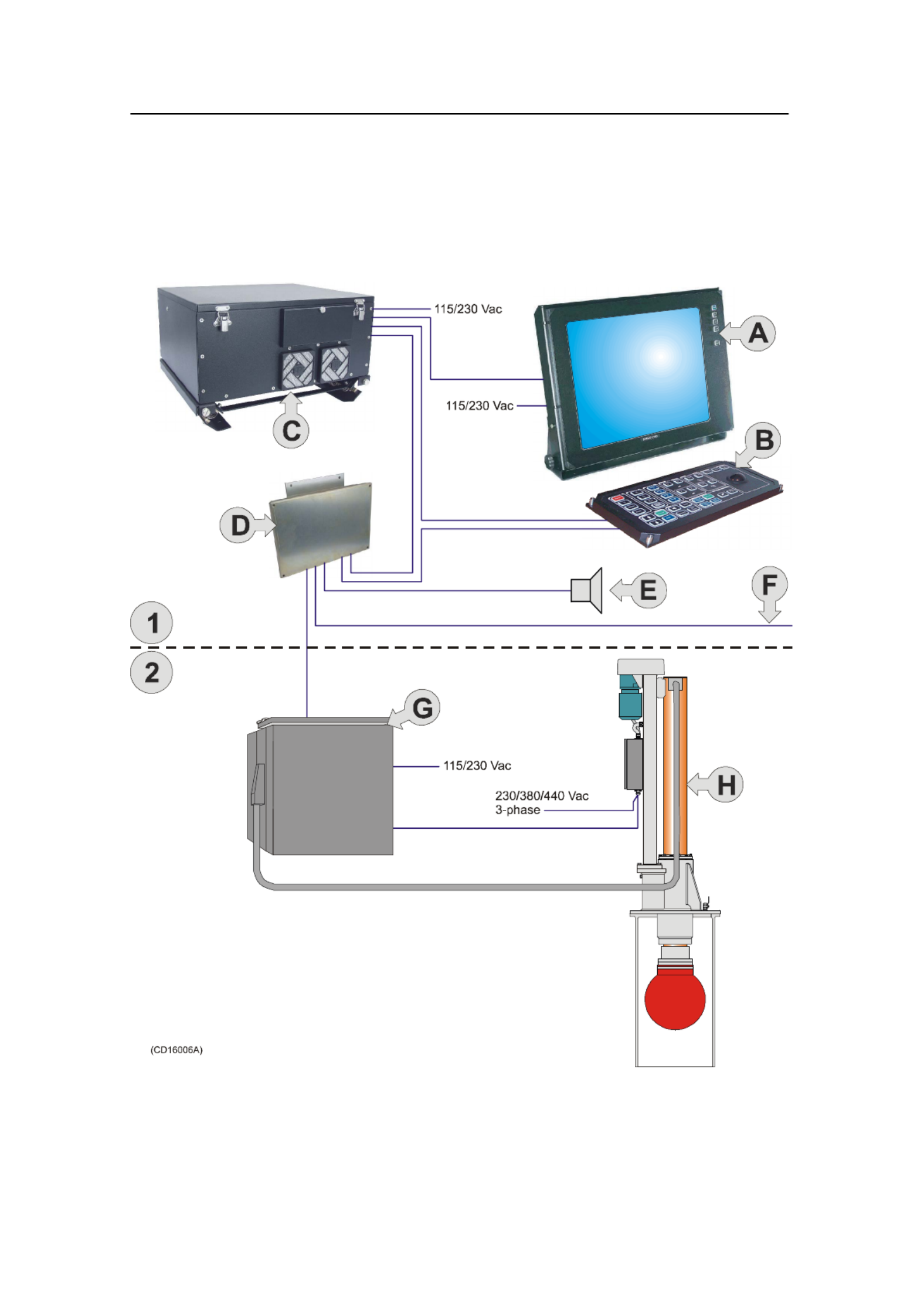
System diagram
A simplified SP60 system diagram is shown.
(A) = Colour display
(B) = Operating Panel
(C) = Sonar Processor Unit
(D) = Sonar Interface Unit
(E) = Loudspeaker
(F) = Multiple interface lines to peripheral equipment
(G) = Transceiver Unit
(H) = Hull Unit
(1) = Wheelhouse
(2) = Sonar room
System description
5
850-164575 / Rev.D

Simrad SP60
6850-164575 / Rev.D
Options
General
The standard SP60 sonar is a single 26 kHz version with beam
stabilization.
The beam stabilization was an optional function until 1 January
2003. After that date, the function was included with the
standard sonar delivery.
The options described below are pre-programmed into the
standard software version, and a code word is required to make
the actual option available. Simrad offers a 1 month free test
period for certain options. Note that the Scientific Output
function is not available for such a test period.
For a permanent installation of a chosen option, a new code
word will be released from Simrad when the option is ordered.
Triple- or multiple-frequency
In addition to the standard 26 kHz frequency, options are
available for triple and multiple frequencies.
• In the triple-frequency version, you can select between 24
kHz, 26 kHz and 28 kHz.
• In the multiple-frequency version you can select from 11
frequencies from 20 to 30 kHz in 1 kHz steps.
These selections are particulary useful when it is necessary to
suppress interference from other sonars.
Scientific output
The Scientific Output is designed for research purposes. When
activated, the following data are available on an Ethernet (LAN)
output:
• Beam data
• Target data
• Own ship data
• Gear data
The scientific output option may also include software for a
Scientific Data Logger.
Note that this option is not available for a free test period.
Related topics
→ Code words, procedure, page 53

System description
7
850-164575 / Rev.D
Functional description
Introduction
The basic principles of the SP60 sonar are unique because of the
128 separate transmitter and receiver channels with their
transducer elements spread around on the spherical transducer
array.
The transmission, reception and data processing are under
computer control, and the powerful capabilities of the sonar are
the results of sophisticated digital signal processing software
and state of the art hardware.
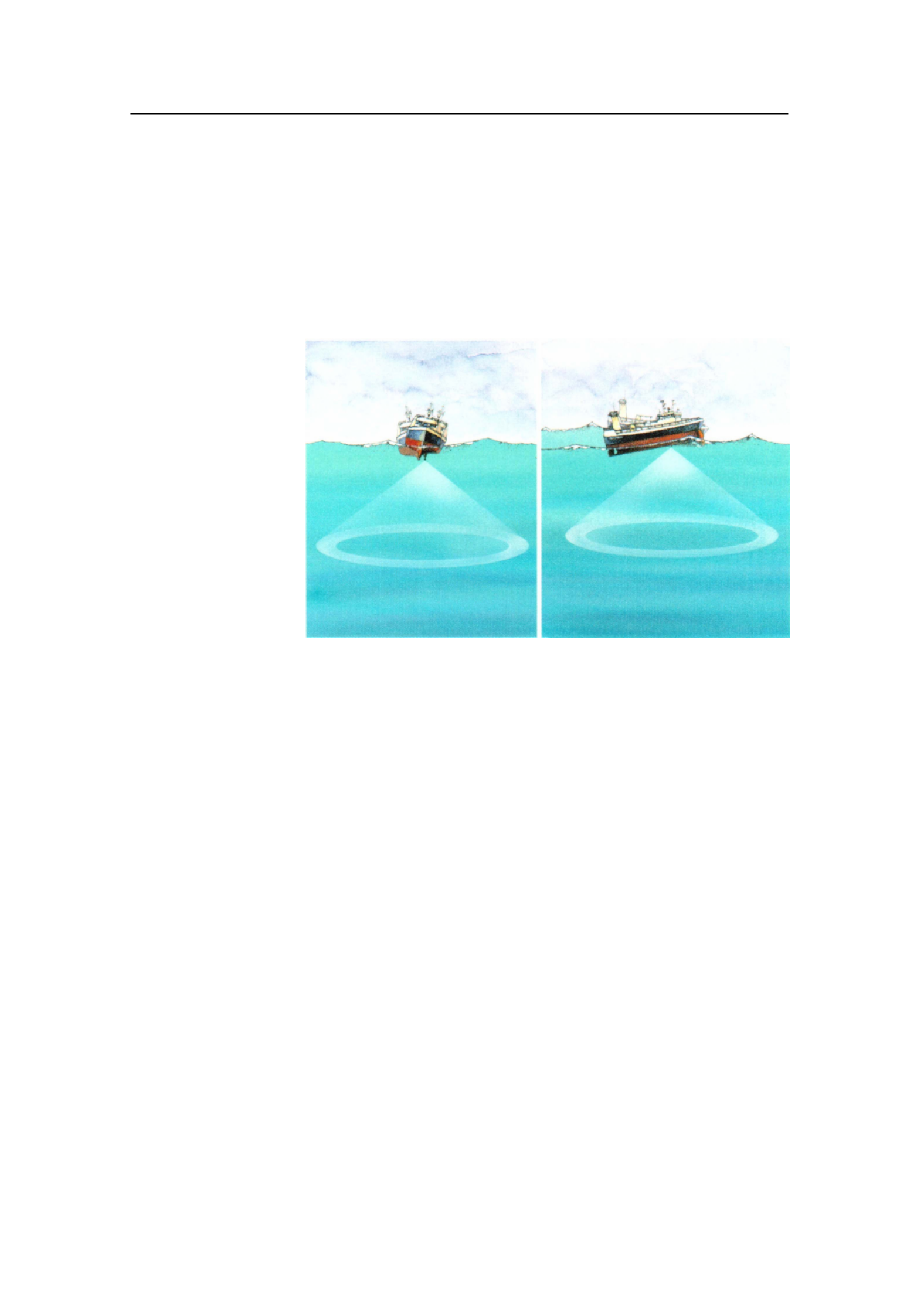
Functional principles
When the Omni beam is tilted, the total beam picture can be
compared with folding an umbrella, which means that all beams
in 360 degrees around the vessel have the same tilt angle.
Omni beam
principle
The beam can be tilted from +10 up to -60 degrees down.
In addition to seeing the target from above, it is also possible to
see the target from the side, by using the vertical slice
presentation. In this case the beam covers a continuous vertical
beam from 0 to -60 degrees in one transmission.
This vertical slice, which is presented by the white audio line in
the horizontal picture, can be selected to any bearing by the
manual training control. The combination of the Omni mode
and the vertical slice will give an optimal visualization of the
catch situation.

Simrad SP60
8850-164575 / Rev.D
60 degrees vertical
slice
Omni/Vertical
combination
In addition to the Omni picture, the vertical slice is especially
useful for visualizing the vertical distribution of a school of fish.
In that way, it is not necessary to go over the target to see the
distribution on the echo sounder, which often results in a
spreading of the school.
System description
9
850-164575 / Rev.D
Stabilization system
When the beam stabilizer is activated, both horizontal and
vertical beams will be stabilized electronically for roll and pitch
movements up to ±20 degrees. The beam direction will then
change continuously according to the vessel’s movements, and
secure an optimal contact with the targets even in rough seas.
Stabilization
system
Reception
A great effort has been made to reduce unwanted noise to get a
clean and stable echo presentation. To achieve this goal the
sonar receiver has the following filtering possibilities:
FM Correlation filter
In addition to the traditional single frequency transmitting
method, the SP60 sonar is equipped with an FM correlation
mode.
In FM mode each transmission pulse contains up to eight
different frequencies, and the receiver makes a spectrum
analysis and compares the received echoes with the transmitted
frequency code. This provides a filtering effect, which
efficiently reduces interference, noise and reverberation. In
addition to giving a clean and stable echo presentation, this will
normally also increases the sonar’s detection range
Frequency selection (Option)
The optional triple- and multiple frequency selections can be
used for suppression of interference from other sonars.

Simrad SP60
10 850-164575 / Rev.D
However, the sound absorption in salt water increases with the
frequency, thus giving the lower frequencies a longer detection
range.
Related topics
→ Frequency options, page 6
AGC (Automatic Gain Control)
This control will automatically adjust the gain in the
preamplifiers depending on the strength of the incoming echo
signals. The strength of the filter can be selected in the menu.
Note that the AGC senses the echo strength in five fixed
directions, and use this as a basis for adjusting all the receiver
beams.
RCG (Reverberation Controlled Gain)
The RCG filter senses the noise level (reverberation, propeller
noise, etc.), and adjusts the gain individually for each of the 64
receiver beams in order to eliminate noise on the display. The
strength of the filter can be selected in the menu. With
maximum strenght is selected, the RCG will effectively reduce
the bottom in shallow water, while variations on the bottom will
be displayed.
Note that scattered fish can be perceived as reverberation. The
RCG filter must therefore be used with care if scattered schools
are to be detected.
PP Filter
The SP60 sonar is equipped with a ping-to-ping filter to give a
clean and steady presentation by reducing the interference and
noise. This filter compares the echoes from a selected amount of
transmissions (pings), and an echo has to be present in the
selected amount of pings in order to be presented on the display.
Note that in rough seas, when the beam easily can miss the
target in several pings, the PP filter must be used with care.
TVG (Time Variable Gain)
The TVG function controls the gain of the receiver so that a
school with a given size and density is presented with
approximately the same strength on the display, inside the
regulated TVG range. This can also be seen as a filter, because it
reduces the noise close to the vessel.
The regulated strength of the TVG can be selected in the menu.
Transmission
The transmitting is controlled by the signal processor in the
Transceiver Unit. The parameters you have chosen are used.

System description
11
850-164575 / Rev.D
There are 128 separate transmitters in the unit distributed on
four transceiver circuit boards. Each transmitter is individually
addressed and controlled from the signal processor. The
controlled parameters include power output and time delay for
each transducer element in order to form a beam with the
selected tilt angle.
When the stabilisation system is active, the tilt angle for each
beam will automatically be corrected relative to the vessel’s
pitch and roll movements.

Simrad SP60
12 850-164575 / Rev.D
Peripheral equipment
The SP60 sonar requires connection to a speed log and a course
gyro. An inaccurate log or gyro input will cause inaccurate
indication of the vessel and target movements.
In addition to log and gyro, the following peripheral equipment
can be connected to the sonar.
• A (D)GPS may be connected to the SP60 sonar to establish
the vessels position and provide cursor and marker latitude
and longitude.
• Simrad echo sounders (EQ, ES and EK Series) provides a
bottom plot on the catch data page.
• Simrad PI32 Net Monitoring system provides the net depth in
digits and bars on the catch data presentation.
• Simrad trawl instrumentation; FS 900, FS 3300 or ITI
- FS 900 and FS 3300: The trawl will be displayed in
correct depth.
- ITI: The trawl will be displayed in correct size, depth,
distance and bearing.
• A Current meter system will indicate the current speed and
direction for up to three different depths in the sonar picture.
• A radio buoy system (GPS type) will provide the
geographical position of the buoy(s) in the sonar picture.
For connection of any of this peripheral equipment, contact your
local dealer.

Display modes
13
850-164575 / Rev.D
DISPLAY MODES
Introduction
This chapter describes the SP60 display modes. The various
modes represent the graphical presentation of sonar data. Nine
different display modes are generated to present the best
possible presentation and flexible choices for a large range of
user applications.
Topics
→ Bow Up, page 14
→ North Up, page 15
→ True Motion, page 16
→ 180
°
/ Audio, page 17
→ 270
°
/ Vertical, page 18
→ Bow Up / Vertical, page 19
→ True Motion / Vertical, page 20
→ Dual 1, page 21
→ Dual 2, page 22
Display mode selection is made on the second menu button in
the main menu. The four first display modes shown can also
easily be selected with the four Mode buttons on the Sonar
Operating Panel.
Note that the descriptive order of the display modes in this
chapter has been chosen only to simplify the descriptions. In
operational conditions, the order of the display modes depends
on the selected gear (seine net, bottom trawl or pelagic trawl)
This is because different initial display modes are used for easy
selection by the four Mode buttons on the Sonar Operating
Panel. The order of these display modes can easily be changed
in the Sort Mode menu.
All the display modes in the following chapters are shown
without echoes.
Related topics
→ Mode buttons, page 27
→ Sort Modes, page 68

Simrad SP60
14 850-164575 / Rev.D
Bow Up
When Bow Up mode is selected, the vessel symbol is stationary
on the screen with the bow pointing upwards. The echo
presentation covers 360 degrees around the vessel, and all
echoes are updated for every ping. The distance from the vessel
symbol to the outer echo ring is equal to the selected range.
The movement of the echoes across the screen are controlled by
a combination of the vessel’s course and speed and the target’s
own movements.
Related topics
→ Cosmetics, page 50
Display modes
15
850-164575 / Rev.D
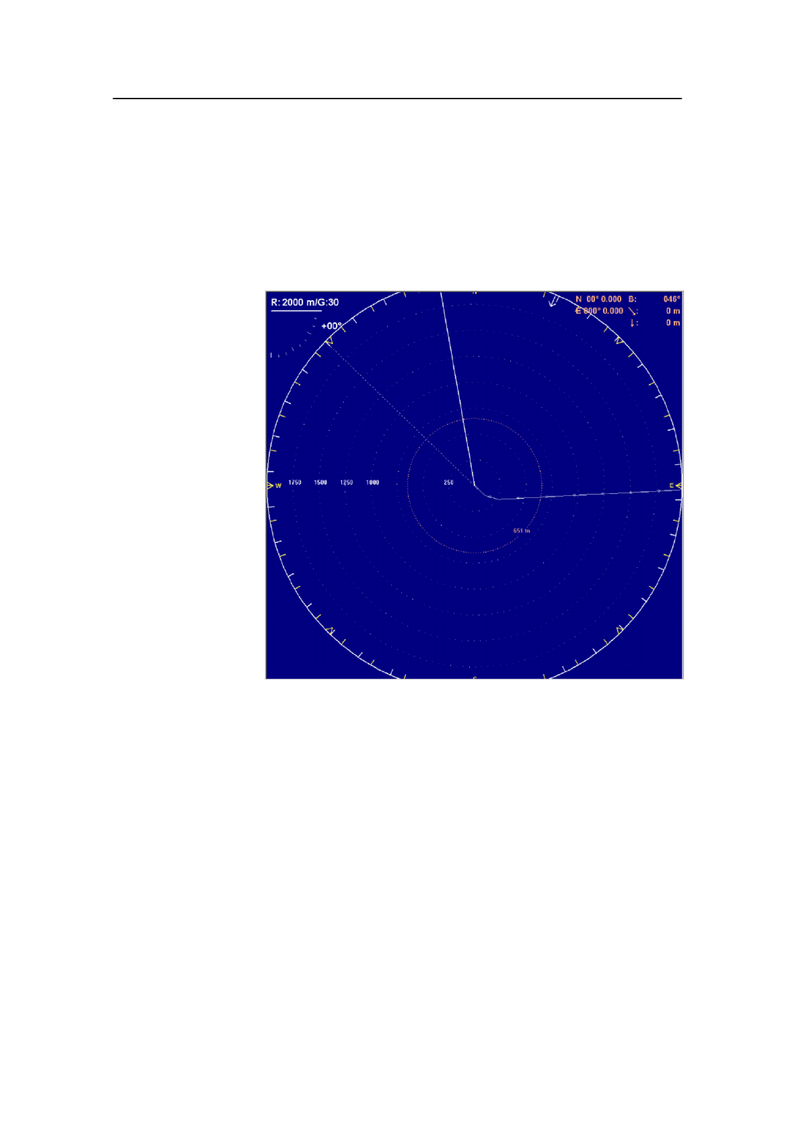
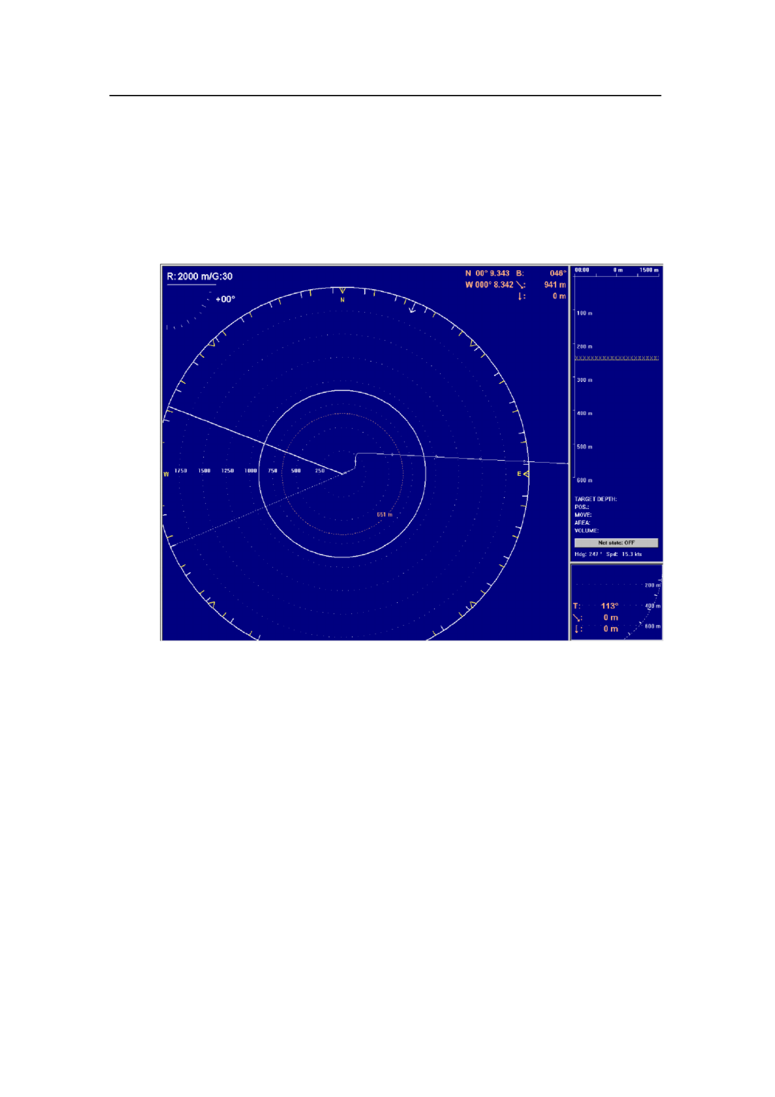
North Up
When the North Up mode is selected, true north is always up
on the screen. The vessel symbol is stationary with the bow
pointing in the vessle’s course direction. The movement of the
echoes across the screen are controlled by a combination of the
vessel’s course and speed and the target’s own movements.
Related topics
→ Cosmetics, page 50
Simrad SP60
16 850-164575 / Rev.D
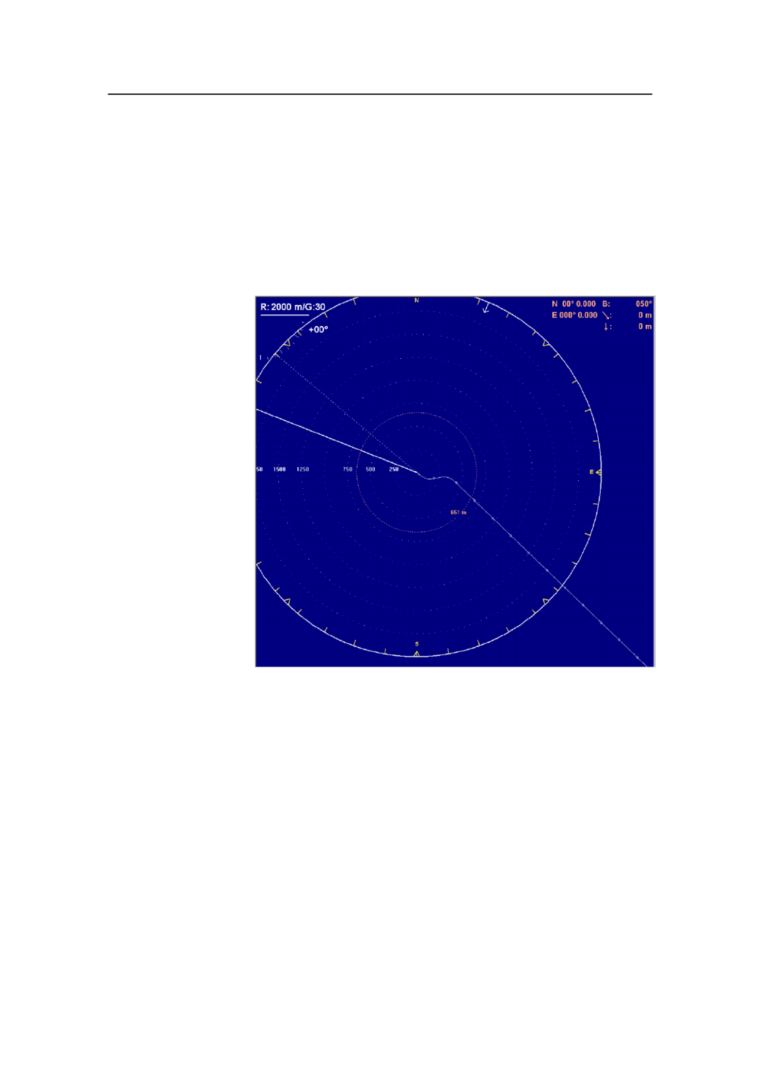
True Motion
When the True Motion mode is selected, the picture is locked
to a geographical position, where the vessel moves around the
screen according to its present course and speed. All echoes are
always presented in their correct position relative to the vessel,
and their movements on the screen will be a true representation
of the movements of the targets through the water.
When the vessel symbol reaches the edge of the screen, it will
automatically be moved back to the centre, or to a position
determined by the Off Centre button. This position is reset to
the screen centre whenever the mode is changed. When you
select Target Track, the target will automatically be moved to
the screen centre.
Related topics
→ Cosmetics, page 50
Display modes
17
850-164575 / Rev.D
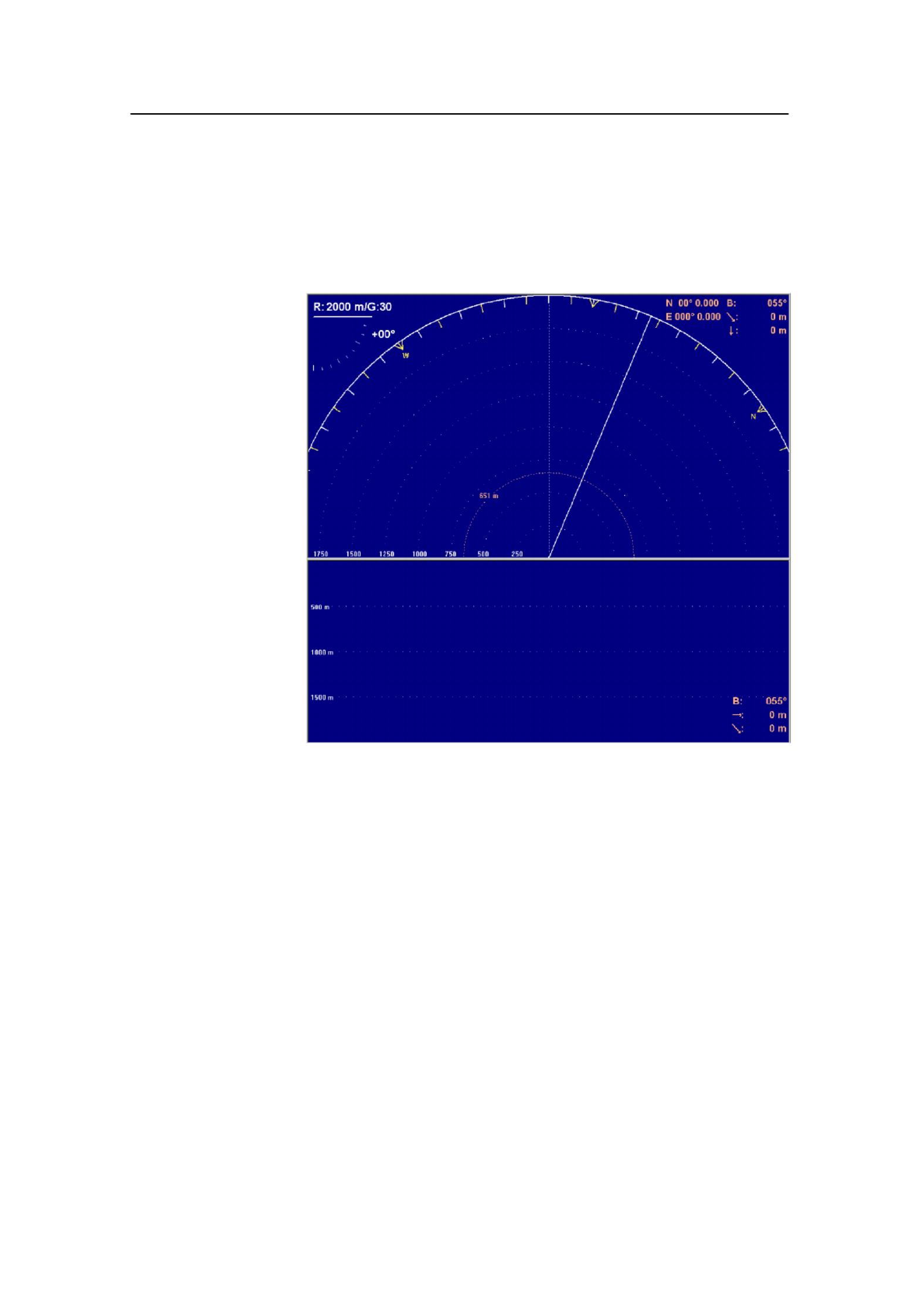
180° / Audio
When the 180° / Audio mode is selected, the upper half of the
screen shows a 180 degrees bow-up presentation, while the
lower part is used for a recording of the audio channel.
The audio channel is shown with a continuous white line in the
horizontal picture, and it can be trained in any direction. The
recorded echoes are a direct replica of the echoes under the
white audio line. As the audio channel is recorded over a period
of time, this mode is especially useful for detection of weak
echoes mixed with reverberation or noise.
The information recorded by the audio channel is always stored
in the computer, even if another mode is selected. That means
that this recording will always be presented when selecting the
180° / Audio mode. Note that the vessel symbol can be moved
to any position in the horizontal view with the cursor and Off
Centre button.
Related topics
→ Cosmetics, page 50

Simrad SP60
18 850-164575 / Rev.D
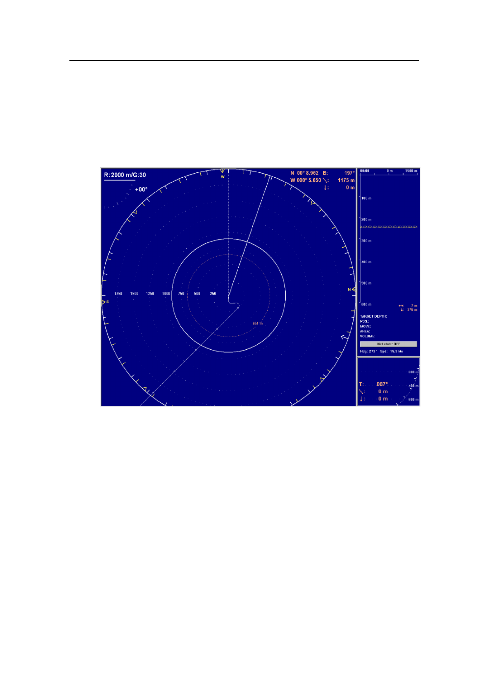
270° / Vertical
The 270° / Vertical mode is specially designed for purse
seining. The vertical half slice is displayed in the lower left
corner for normal setting with the net on the starboard side. If
the net is set on the port side, the 60 degrees vertical slice will
be displayed in the lower right hand corner.
With this presentation, it is easy to keep the best contact with a
school in both the vertical and horizontal presentation, and to
determine its size distribution. The position of the school
relative to the bottom is another important information provided
by this presentation. The Catch data presentation for purse
seining is shown on the right hand side. It shows all the net data
relative to the target and the bottom, as well as all available
target data.
Related topics
→ Cosmetics, page 50
Display modes
19
850-164575 / Rev.D
Bow Up / Vertical
When the Bow Up / Vertical mode is selected, the picture is
divided into three sections; where the left side is a bow-up
presentation similar to the bow-up presentation previously
described.
The upper part on the right hand side is a catch data
presentation, while the lower part is a 60 degree vertical slice
presentation.
Related topics
→ Cosmetics, page 50
Simrad SP60
20 850-164575 / Rev.D
True Motion / Vertical
When the True Motion / Vertical mode is selected, the picture
is divided into three sections; where the left side is a True
motion presentation similar to the true motion presentation
previously described.
The upper part on the right-hand side is a Catch data
presentation, while the lower part is a 60 degrees Vertical slice
presentation.
Related topics
→ Cosmetics, page 50

Display modes
21
850-164575 / Rev.D
Dual 1
The Dual mode is a kind of “two sonars in one” operation,
where each presentation is updated for every second
transmission. All settings can be set individually for each of the
two presentations. This makes the dual mode especially useful
for optimizing settings by directly comparing the two
presentations.
To optimize the horizontal settings, use the Horizontal menu to
try different settings in the upper picture. These settings are
automatically transferred to the other modes.
The dual operation may also be used for other user applications,
where different range, tilt, frequency and other parameters can
be selected.
Related topics
→ Cosmetics, page 50

Simrad SP60
22 850-164575 / Rev.D
Dual 2
The Dual 2 mode is very similar to the Dual 1 mode previously
described, but the “two sonars” are presented next to each other.
All settings can still be set individually for each of the two
presentations.
Related topics
→ Cosmetics, page 50

Sonar Operating Panel
23
850-164575 / Rev.D
SONAR OPERATING PANEL
Introduction
You may enter operational commands directly on the Sonar
Operating Panel. Sonar functions may also be accessed and
activated using the menu field on the display and the trackball
on the operating panel.
Frequently used functions are directly accessed by the
designated control buttons. These are grouped according to their
purpose.
Sonar Operating Panel
POWER
Up
Middle
Down
MAIN SW. SYMBOL
Gain
H - Range
H -
Gain
V - Range
V -
Gain
H + Range
H +
Gain
V + Range
V +
MODE
Mode
1
GAIN
Mode
2
Mode
3
Mode
4
RANGE CURSOR
SelectMenu View Object
SONAR OPERATING PANEL
TILT
Manual
Auto
VARIO US
Zoom
Record Off
Centre
Position
Track Manual
Target
Track Auto
Search
TRAIN
(CD5377B)
SIMRAD
A thorough understanding of system functions and controls is
necessary to optimize overall performance. Sonar conditions
vary, sometimes drastically, and it is not possible to identify
settings that will provide the best data at all times. Careful study
of the information in this manual is highly recommended,
preferably while exploring the sonar’s various functions. System
operation is a dynamic activity requiring regular adjustments
and fine tuning to achieve the best possible results under varying
environmental conditions.

Simrad SP60
850-164575 / Rev.D
Main switch
Main switch functions control power to the sonar, hoisting and
lowering of the transducer and indicates the transducer’s current
position.
Power
Pressing for approximately two seconds powers up thePower
sonar. The adjacent green LED blinks while the Sonar Control
Unit boots up, and remains illuminated once the system is
operational.
Before the sonar can be powered down, the transducer must be
in the Up position. Pressing the Power button for approximately
two seconds secures power to the unit which is confirmed by the
adjacent green LED being extinguished.
Up
Raises the transducer to its upper position. The adjacent green
LED blinks while the transducer is raised and remains
illuminated once it is housed safely inside the hull of the vessel.
The green blinking LED will also be accompanied by an audible
signal.
Middle
Raises or lowers the transducer to its middle position.
The physical location of the middle position can be defined in
the Transducer parameter dialogue.
Down
Lowers the transducer to its lower position. The adjacent green
LED blinks while the transducer is lowered and remains
illuminated when lower position is reached. The green blinking
LED will also be accompanied by an audible signal.
Related topics
Transducer,page 144

Sonar Operating Panel
850-164575 / Rev.D
Symbol
The Symbol functions provide on-screen graphic references for
targets, own ship and fishing gear.
(A) Target marker
To mark a target, move the cursor over it and press
the button. A triangular symbol with a
corresponding number will appear on the screen
over the target.
Position data for the defined markers are displayed
in the Objects menu.
Note that the system continues to track the markers
even when outside the sonar range.
The Target marker function can also be used for
manual target tracking as the system is designed to
calculate the speed (S), course (C) and distance (D)
between the last two chosen targets.
The Target marker data is displayed in white
figures for three minutes in the lower right hand
corner of the horizontal presentation. This function
is also an effective method for determining the
distance between two selected points on the screen.
(B) Own ship marker
The “own ship” button produces a square symbol on the screen
at the vessel’s current location when the button is pressed. The
own ship marker’s position data is displayed in the Objects
menu.
(C) Circle marker
This marker may be used to estimate the size of a school of fish
or as an indication of the size of the purse seine. To activate the
function, move the cursor to the desired position and press the
button. A circular symbol will appear on the screen at the
chosen location. The size of the symbol is equal to that of the
purse seine selected.
(D) Gear symbol
The gear symbol may be either a purse seine circle or a trawl
symbol depending on the parameter chosen by the Gear button
in the Setup menu. The selected gear symbol will be displayed
in yellow.

Simrad SP60
850-164575 / Rev.D
Seine circle
This is a useful aid in planning the shooting of the purse seine. It
is used as follows:
1Press the Gear button.
- The purse seine circle will appear on the forward end of
the ship symbol on the corresponding side of the vessel
selected in the Setup menu. The circle will follow the
vessel’s movements.
2At the moment the seine is shot, press the Gear button
again.
- The purse seine circle will remain stationary and
indicate the ideal path for setting the seine. Three
square symbols on the ship’s course line indicate the:
shooting, one half, and the end of the seine positions.
Three different nets can be pre-programmed in the
Gear menu.
3Press the Gear button to delete the Purse Seine circle.
Trawl symbol
This is a useful aid in providing an overview of the trawl
operation.
Trawl data can be set manually using the menu or automatically
by interfacing the Simrad FS trawl sonar or ITI trawl
monitoring system with the sonar.
In the manual mode the trawl symbol will be displayed with
the selected size, depth and distance.
When the FS900 or FS3000 trawl sonar is connected, the
trawl symbol will automatically be displayed with the correct
depth in the vertical modes.
When the ITI trawl system is connected, the trawl symbol
will be displayed with the correct distance, bearing and
depth. If required, the trawl opening, ambient water
temperature, and trawl-filling indicator may also be
displayed.

Sonar Operating Panel
850-164575 / Rev.D
Mode
The four Mode buttons can be used to select either the four
favourite display modes or user settings. The set up the buttons
to choose modes or settings, select Mode Buttons in the
Display menu.
Depending on the selection you make in the Mode Buttons
menu, you have two options:
To select a mode, use the Mode button on the top of the
menu, or press one of the four Mode buttons. Frequently
used operational modes that are task specific to particular
phases of the fishing operation can be pre-defined in the Sort
modes menu. For example, Mode 1 may be used for the
search phase, forMode 2 for the evaluation phase, Mode 3
the catch phase, and Mode 4 for dual operation.
To select a user setting, you can select User Settings on the
the Setup menu, or you can use one of the four Mode
buttons. The different user settings are created and
maintained in the User Setting parameter dialogue. To
choose user setting assignment to the four buttons, sort the
list of users alphabetically.
Related topics
Sort Modes, page 68
Display Modes, page 13
User Settings, page 148
Mode Buttons, page 115

Simrad SP60
850-164575 / Rev.D
Gain
Gain controls are specified as either horizontal or vertical.
Horizontal gain
The two upper buttons control receiver gain
effecting the horizontal presentation of the sonar.
The level of gain selected is display in the
Horizontal menu and on top of the tilt indicator in
the upper left-hand side of the display. It has 51
selectable values numbered from 0 to 50 and may be
changed in steps of 1 dB.
Vertical gain
The two lower buttons control receiver gain
effecting the vertical presentation of the sonar. The
level of gain selected is display in the Vertical
menu. It has 51 selectable values numbered from 0
to 50 and may be changed in steps of 1 dB.
Sonar Operating Panel
850-164575 / Rev.D
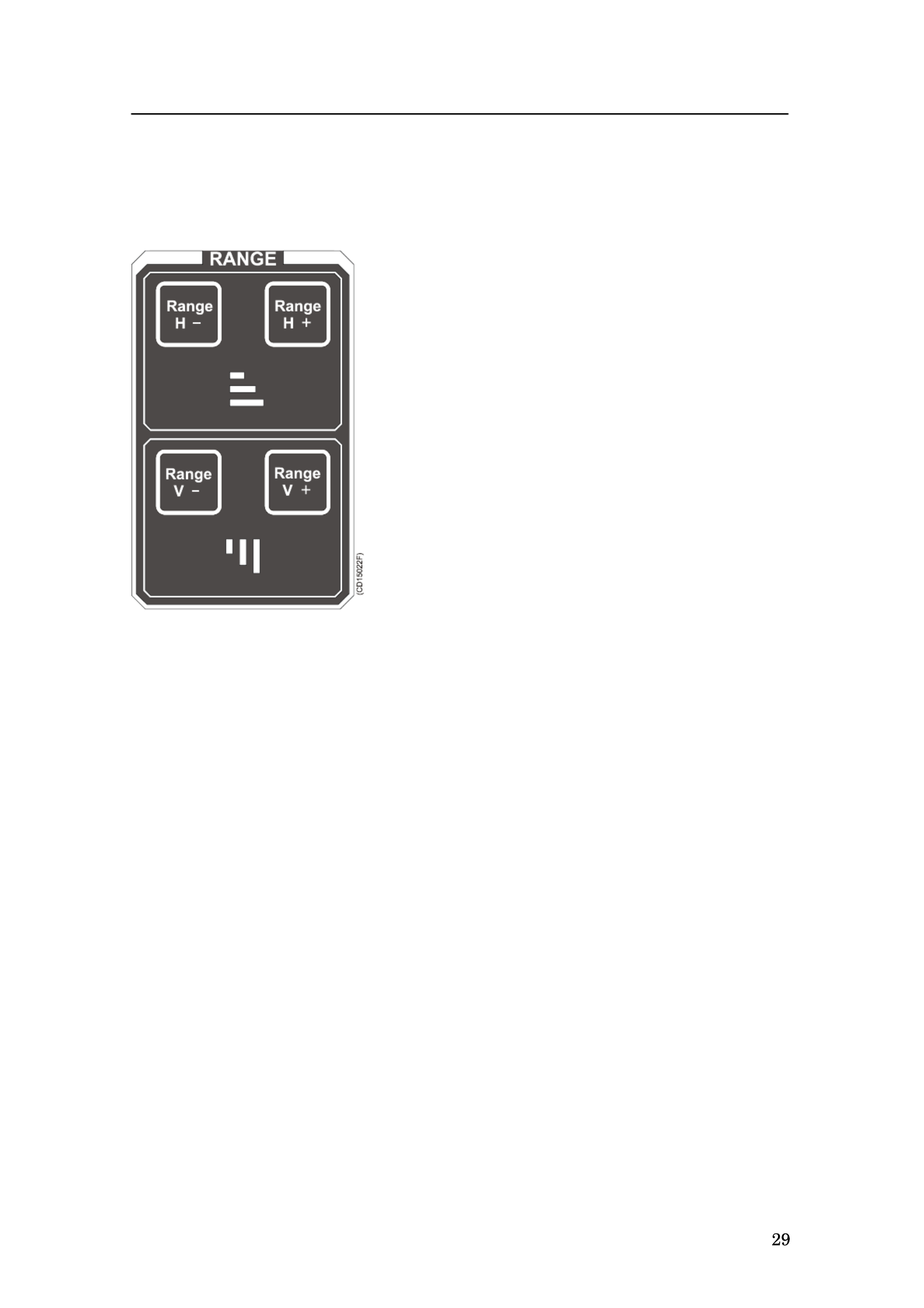
Range
Range controls are specified as either horizontal or vertical.
Horizontal range
The two upper buttons control the horizontal range.
The range selected is displayed in the Horizontal
menu, and on top of the tilt indicator in the upper
left corner of the display.
Vertical range
The two lower buttons control the vertical range.
The range selected is displayed in the Vertical
menu.

Simrad SP60
850-164575 / Rev.D
Cursor
The cursor is used for on-screen cursor orientation and menu
operation.
Menu
The Menu button is used for
selection between Menu or Full
Screen presentations. When the
main menu is displayed, the echo
presentation will be reduced
correspondingly. In full screen
presentation, the full dimension of
the screen is used for the echo
presentation.
When the full screen echo
presentation is displayed, the
cursor may be used to activate the
menu field by moving it to the left
or right extremes of the screen.
Moving the cursor outside the
menu field will hide the menu.
Select
The Select button is used to execute a selection. This
corresponds to the left button on a standard mouse.
View
The View button activates the View pop-up menu for the
selected display window. This button corresponds to the middle
button on a standard mouse.
Object
The Object button activates the Object pop-up menu for the
selected display window. This button corresponds to the right
button on a standard mouse.

Sonar Operating Panel
850-164575 / Rev.D
Trackball
The trackball controls the cursor. The cursor changes
appearance in relation to its location on the screen:
An Orange cursor in the echo field.
An arrow in the menu field.
A negative or positive sign at each end of the menu buttons.
The negative or positive sign indicates the direction in which
the corresponding parameter values will be changed when the
Select button is pressed.
Related topics
Menu and full screen presentations, page 41
View pop-up menu, page 70
Object pop-up menu, page 72
Menu buttons, page 45

Simrad SP60
850-164575 / Rev.D
Train
The audio channel is displayed as a continuous white line. It can
be trained either manually or automatically. The bearing angle is
displayed in the upper right-hand corner of the display, indicated
relative to the bow.
Manual
In the Manual mode the train left (arrow) or train right (arrow)
buttons are used to direct the audio line to the desired bearing.
Auto search
In the Auto Search mode the sonar will automatically search
within pre-set sector limits with the selected audio line
designating the centre of the search. The search sector is
displayed on the bearing card with two white angular symbols.
The search sector is adjusted by pressing and holding the
Auto Search button and simultaneously pressing the train
left (arrow) or train right (arrow) buttons .
The Automatic Search function is overridden when either
the train left (arrow) or train right (arrow) buttons are pressed
and will continue once released. The present bearing at the
moment either button is released will become the centre of
the search.
Position track
The Position Track function is only available when both a
course gyro and a speed log are interfaced with the sonar
system.
To track a fixed position, place the cursor over the desired
location and press the Position Track button. A geographically
fixed circle will appear on the display, and its position will
automatically be tracked by the system with respect to the
bearing and tilt angle.

Sonar Operating Panel
850-164575 / Rev.D
When the Auto Tilt function is activated in the Position Track
mode the tilt search centre is automatically adjusted with regard
to the distance to the tracked position.
Target track
To track a target, place the cursor over the desired location and
press the Target Track button. A circle will appear on the
display and its position automatically tracked by the system
using the strongest echo centred in the ”window” represented by
two lines on the audio line. The “window’s” size may be
selected by the Track Window button in the Setup menu.
The vector originating from the target’s centre indicates its
course and speed. The length of the vector increases relative to
the target’s speed. One knot is represented by a small mark on
the vector. A course line can also be displayed showing the
target’s track.
Target tracking symbols and data are displayed with a light
violet colour. In addition to the information on the Catch data
page, the speed, course and distance for some modes are found
in the lower left hand corner of the screen.
In Manual tilt mode, the tilt angle will automatically be
adjusted with respect to the distance to the tracked target.
When the Auto Tilt function is activated in the Target Track
mode, the tilt search centre is automatically adjusted with regard
to the distance to the tracked position.
Note Manual training overrides the Target Tracking function.
Sonar Operating Panel
35
850-164575 / Rev.D
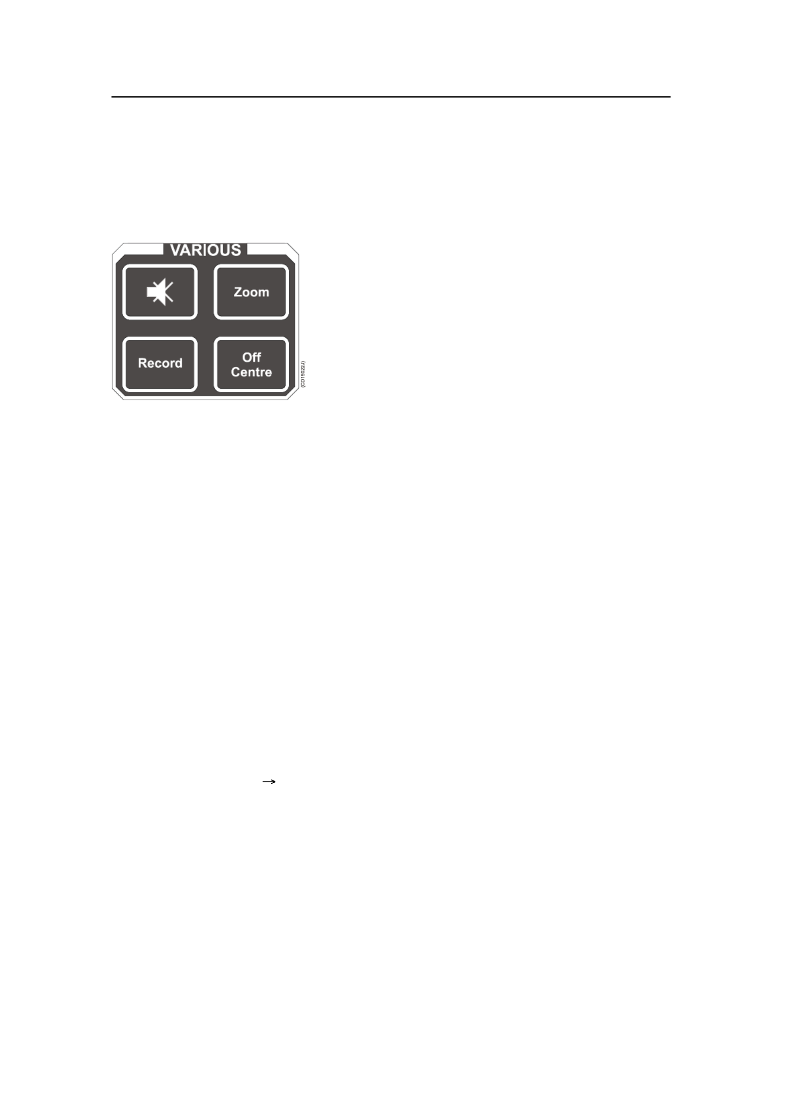
Various
The buttons grouped under various are Zoom, , Record Mute
and Off Centre.
Mute
The Mute button is used as to activate and
deactivate the echo audio channel, and to
acknowledge audible alarms. The Mute function is
also available on the Display menu.
Record
The record function is used for storing either a
sequence or single display picture. Sequential or
single storage options are preset in the Store/Recall
menu (available from the menu).Setup
If sequential store mode is selected, Record is used for starting
and stopping the storage. If single shot storage is selected a new
picture is storage each time the button is pressed.
Zoom
The zoom function magnifies an area of the display by
positioning the cursor in its centre and pressing the Zoom
button. The Zoom button works as a toggle switch for on/off of
the zoom function.
Off centre
The Off Centre function moves the Own vessel symbol to the
cursor’s position on the display. This adjusts the presentation to
fill the screen accordingly.
Related topics
Store/Recall menu, page 65
Operation
850-164575 / Rev.D
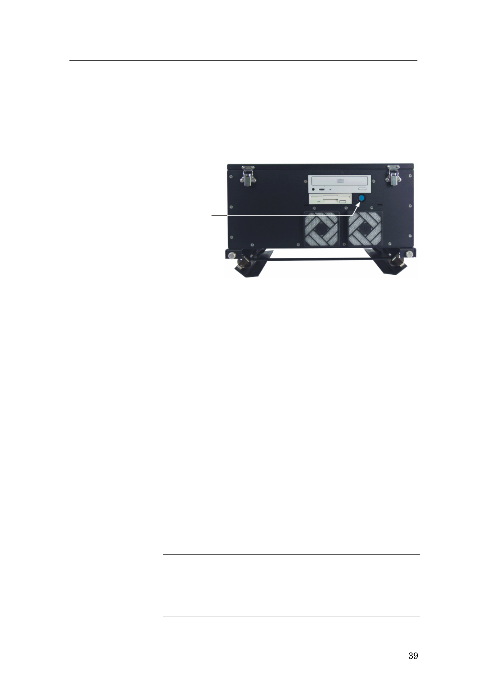
Disconnected mains
In case of power failure, or if the mains plug on the Sonar
Processor Unit has been disconnected, the sonar must be started
by pressing the start switch S101. This switch is located behind
the small front panel on the Sonar Processor Unit.
The location of the S101
switch on the front of the
Sonar Processor Unit.
(CD15006)
S101
Design change
On sonars shipped from Simrad before August 2003, the
APC10 Sonar Processor Unit is used. This unit is also equipped
with an “on/off” switch behind a front panel. It has also an
additional “master on/off” switch on its rear panel. Instead of
disconnecting the mains plug, this switch can be set to “off”.
Stop procedure
1Press the Up button on the Sonar Operating Panel to hoist
the transducer to the upper position.
- The green LED next to the button will flash, and an
audible signal indicates that the transducer is hoisted.
When the upper position has been reached, the LED
will illuminate continuously, the audible signal stops,
and the upper button in the Status menu shows:
Transducer: UP.
2Press and hold the Power button approximately two
seconds to switch off the sonar.
3Check that the green LED next to the On/off button
extinguishes.
4Press the Power button on the display monitor to switch it
off.
Warning If the sonar is switched off uncontrolled with the
transducer lowered, the transducer must be
raised by means of the hoist/lower switch in the
Motor Control Unit, or with the hand crank.

Simrad SP60
850-164575 / Rev.D
Procedures for emergency hoisting are provided in the
Maintenance chapter.
Dry-docking safety measures
To prevent inadvertent use of the sonar when dry-docking etc.,
disconnect the mains plug for the Sonar Processor Unit.
Warning Transmitting in air will damage the transducer!
Related topics
Sonar Operating Panel, Main switch. page 24
Manual hoisting and lowering, page 163
Status, page 137

Operation
850-164575 / Rev.D
Menu operation
Introduction
The menu system on the SP60 sonar is designed to allow for
easy and fast access to the parameters.
The menu can be removed from the screen.
Some of the parameters (for example Range, )Gain and Tilt
can be controlled both from the button on the menu and from
buttons on the Sonar Operating Panel. The parameter values
shown on the menu buttons will then change according to the
setting made on the panel.
It is also possible to operate the sonar with a standard computer
mouse.

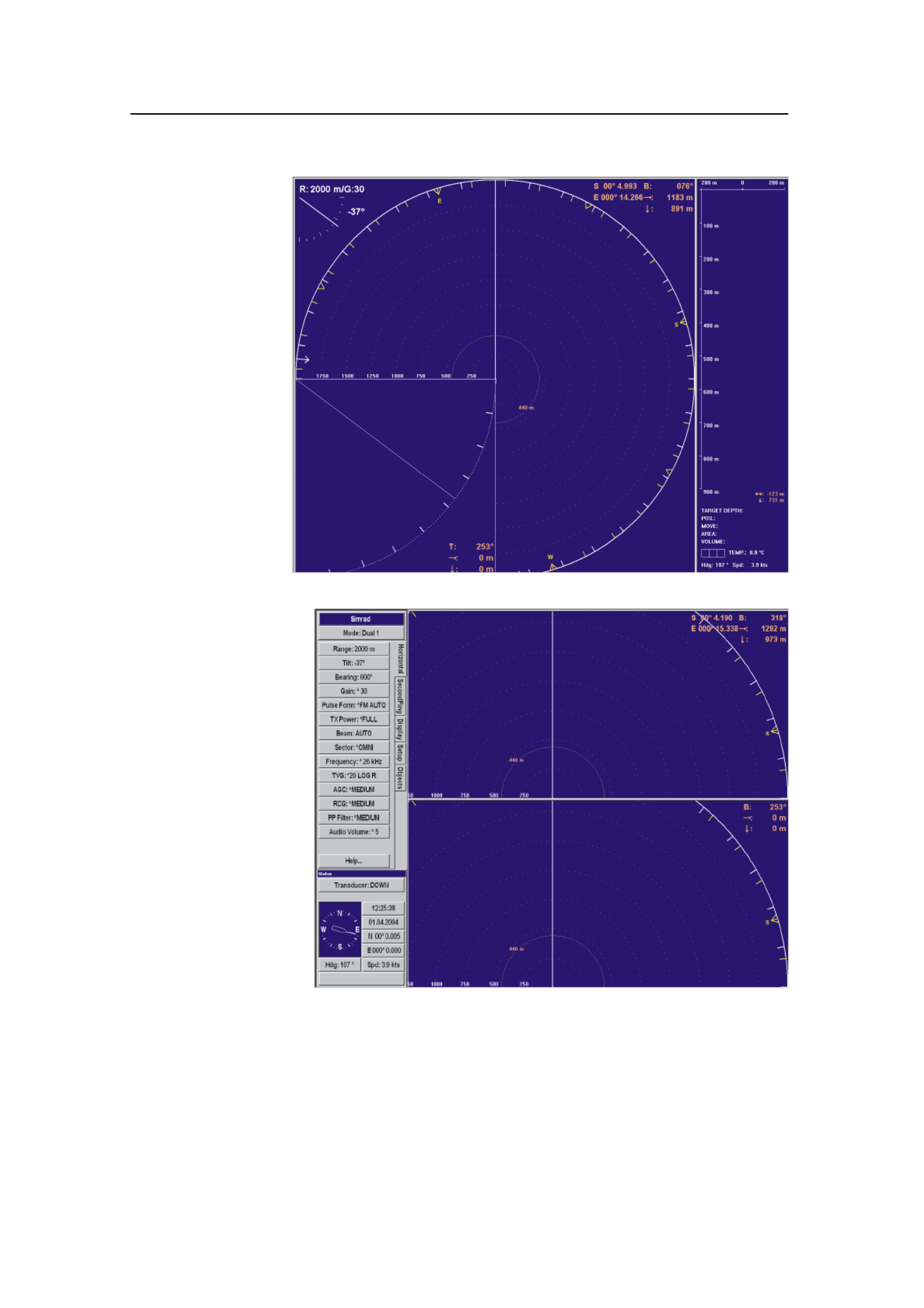
Simrad SP60
850-164575 / Rev.D
Screen presentations
The menu can be set up for permanent display, or available only
when required for parameter alterations. The Menu button on
the Sonar Operating Panel is used to select Menu or Full
Screen presentation.
Typical screen
presentation with
the menu on the
right hand side
(CD15008A)
In Menu presentation, the menu is always shown on the right
hand side of the display, and the size of the echo area will be
reduced. When Full Screen is selected, the echo presentation is
extended to cover the entire display.
A standard menu presentation is shown in above.
A full screen presentation with the menu disabled is shown
below.
Once the menu has been disabled, observe the following
procedure to recall it for temporary use.
1Use the trackball, and move the cursor to the outmost left-
or right hand side on the display.
2Observe the menu appear on top of the echo area, and that
the remaining echo area is not re-scaled.
3Move the cursor outside the menu, and observe that it
disappears.
Operation
43
850-164575 / Rev.D
Full screen
presentation with
the menu hidden
from view
(CD15008B)
Full screen
presentation with
temporary menu
(CD15008C)

Simrad SP60
44 850-164575 / Rev.D
Menu structure
The menu field on the sonar display contains several different
buttons, tabs and parameter dialogues.
(A) Sonar type: The upper “button”
indicates the sonar in operation. You can
not press this button.
(B) Mode selection: The second button is
used to display the current mode. You can
press this button to select a different mode.
(C) Tabs: These selections on the right
hand side of the menu allows you to choose
between the menus applicable for the
current operational mode. The menu field
will provide different tabs for each display
mode. In order to select a new menu, move
the cursor to the tab, and press Select.
(D) Active menu: The next field contains
the main menu. Depending on operational
mode and the menu properties, this menu
can contain a number of buttons or other
information.
(E) Menu button: Each menu button
allows you to define the parameters for the
specific function.
(F) Parameter dialogue: When a menu
button is pushed, the applicable dialogue
with a selection of parameters appears at
the bottom of the menu.
All the tabs, menus and submenus are
explained in chapter Menu.
Related topics
→ Menu buttons, page 45
→ Menus overview, page 56
(CD15009)
A
C
D
E
F
B

Operation
45
850-164575 / Rev.D
Menu buttons
Each menu contains several buttons. Each button shows both
the function and the current parameter. The majority of the
buttons in each menu field have three functions.
• You can select a lower parameter value.
• You can select a higher parameter value.
• You can open the applicable dialogue.
(A) Decrease: Position the cursor on
the left side the button. Observe the
arrow symbol change to a minus
sign: Decrease the parameter by
pressing the Select button.
(B) Increase: Position the cursor on
the right side the button. Observe the
arrow symbol change to a plus sign:
Increase the parameter by pressing
the Select button.
(C) Dialogue: Position the cursor on
the centre of the menu button.
Observe the arrow symbol change to
a menu symbol. Open the parameter
dialogue by pressing the Select
button. The dialogue appears in the
lower part of the menu field,
providing an overview of the
available options.
(C )D15010
+
-
BA C

Simrad SP60
46 850-164575 / Rev.D
Selecting a new parameter value
The menu system is operated by the trackball and the Select
button on the Sonar Operating Panel.
When you have gained more experience, and
have become more familiar with the available
options, you will select the parameters directly
from the “smart” buttons. Use the trackball to
move the cursor, and position it over the
button.
First method:
1Use the trackball to move the cursor to
the right or left side of the button.
Observe that the cursor symbol changes.
2Increase or decrease the option by
pressing the Select button (A).
Second method:
1Use the trackball to move the cursor to the middle of the
button (B). Observe that the cursor symbol changes to a
small menu icon.
2Click the Select button (A) on the Sonar Operating Panel.
Observe the parameter dialogue appearing at the bottom of
the menu (C).
3Use the trackball to move the cursor, and press the Select
button on the Sonar Operating Panel to choose the new
setting (D).
4 ClosePress (E) to close the parameter dialogue.
(C )D15012
C
D
E
B
CURSOR
SONAR OPERATING PANEL
Menu Select View Object
(
CD150 11)
A

Operation
47
850-164575 / Rev.D
The parameter value shown in the button is operational even
without closing the parameter dialogue. This makes it easy to
test the effect of each parameter setting. Note that the
transceiver related parameters will first be in operation in the
next ping.

Simrad SP60
90 850-164575 / Rev.D
Bearing (Display)
The Bearing button is located in the Display menu.
This is simply a selector switch. Click on the button to select
True north or Relative ship. Certain bearing data will change
their values accordingly.
The following bearing data will change when you switch
between the two settings:
• Cursor bearing
• Markers bearing in the Objects menu
• Target positions in the catch data views
Note that there are no indication on any of these readouts to
identify them as relative or true.
All other bearing data remain permanent, and will not change
when you select relative or true bearing.
• Wind direction - always relative to true north
• Audio line - always relative to the ship’s heading
• Ship’s current heading - always relative to true north
• Target’s current heading - always relative to true north
Parameters
91
850-164575 / Rev.D
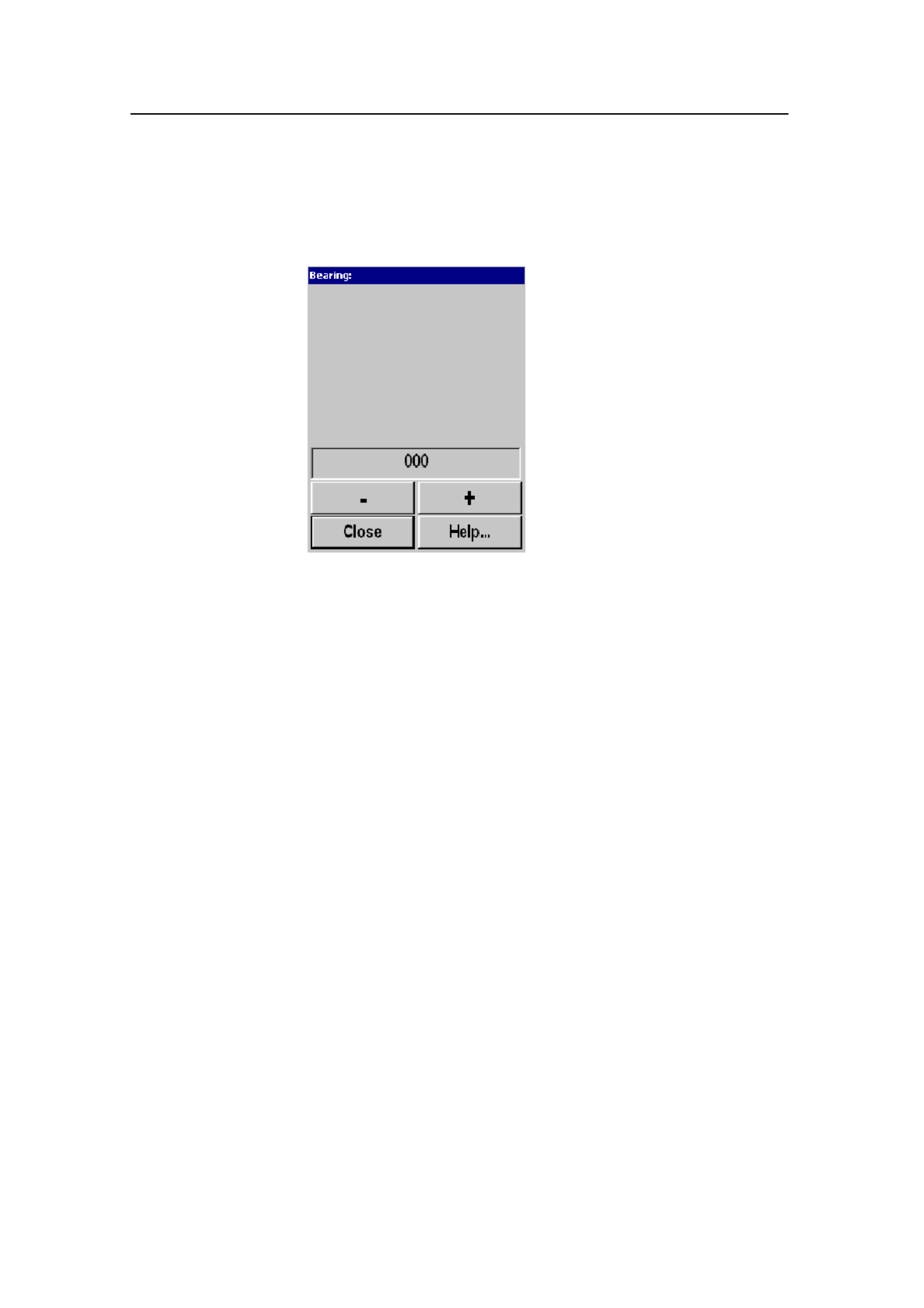
Bearing (Vertical)
The Bearing (Vertical) parameter is accessed from the Vertical
menu.
This dialogue allows you to train the audio channel bearing
manually. The Bearing of the audio channel is normally
controlled with the Train buttons on the Sonar Operating Panel.
The bearing of the vertical slice, which is presented by the white
audio line in the horizontal picture, may also be trained by the
Bearing button in the Horizontal menu.
The following options are available:
- (minus button) - Train left.
+ (plus button) - Train right.
More information about the Train control is provided in the
Sonar Operating Panel chapter.
Related topics
→ Train control, page 32

Simrad SP60
92 850-164575 / Rev.D
Colour Threshold
The Colour Threshold button is located on the Display menu.
The Colour Threshold function is used to reduce the number of
echo colours on the display.
The strength of the echoes is indicated with a scale of 16 or 64
colours. A weak echo has a cold colour (blue), medium echoes
have warmer colours (green, yellow) and strong echoes are
shown with the warmest colours (orange, red). If desired, the
number of colours may be reduced. When you do this, the sonar
witll start with the colour indicating the weakest echoes.
Therefore, by reducing colours, the maximum detection range
will be reduced, because all echoes will normally appear as
weak echoes at long ranges.

Parameters
93
850-164575 / Rev.D
Colours
The Colours button is located in the Display menu.
The colour strength of the echo presentation can be selected
with three different colour scales. Under normal conditions, the
Normal colours will give the best dynamic in the echo
presentation, while Strong colours are preferred for weaker
echoes.
Do not confuse this parameter with the Colour Threshold
setting.
Related topics
→ Colour Threshold, page 92

Simrad SP60
94 850-164575 / Rev.D
Data Source
The Data Source button is located in the Vertical View menu.
The Vertical View menu is are activated by pressing the View
button on the Sonar Operating Panel (or the middle mouse
button) while positioning the cursor in any of the vertical views,
and then selecting View menu on the View pop-up menu.
The Data Source parameter is used to select the bearing source
of the vertical views.
Audio - The vertical slice will follow the trainable audio
channel.
Indicator - The bearing of the vertical slice can be adjusted
independent of the Audio channel.
In addition, the vertical slice may be selected to three fixed
settings: Forward, Aft, or Athwart.

Parameters
95
850-164575 / Rev.D
Dead Reckoning
Dead Reckoning is accessed from the Setup menu.
Dead Reckoning is used to improve the position of the
historical track line from the vessel, relative to the actual
position of the drifting fishing gear.
When OF F, the vessel movement and track line will be
calculated from the GPS data, which then will be relative to the
bottom.
When ON, the gyro and speed log are used to positioning the
vessel relative to the water.
In order to get correct dead reckoning, a doppler speed log must
be connected to the sonar.

Simrad SP60
96 850-164575 / Rev.D
Default Setting
Default Setting is accessed from the Setup menu.
This function makes it possible to delete all the parameters
currently saved in the sonar’s memory, and re-install those
defined by Simrad instead; the factory default settings. These
default settings are identified with an asterisk in the different
parameter dialogues and menus, and will perform well under
normal conditions.

Simrad SP60
98 850-164575 / Rev.D
Display Gain
Display Gain is accessed on the Display menu.
The Display Gain increases or decreases the presentation of the
echo colours on the display. In order to adjust the receiver gain,
refer to the individual Gain parameters accessed in the
Horizontal and Vertical menus.
Related topics
→ Gain, page 107

Parameters
99
850-164575 / Rev.D
Edit Gear (Purse)
The Gear parameter dialogue is accessed on the Setup menu.
Each of the available options in the Gear dialogue can be edited
using the Edit button. When a purse has has been selected, this
parameter dialogue is provided.
These parameters allows you to define the depth and the length
of your purse seine, as well as which side of the vessel it is
positioned.
Depth
This function allows you to enter the depth of your purse seine.
When the Gear symbol is selected, the depth of the purse seine
will be shown on all vertical views.
Length
This function allows you to enter the length of your purse seine.
When the Gear symbol is selected, the seine circle will be
shown in correct size. A dedicated parameter dialogue is used to
make this setting.
Throw Side
This function is used to position the seine circle on the port or
starboard side of the vessel. A dedicated parameter dialogue is
used to make this setting.
Related topics
→ Gear, page 108
→ Sonar Operating Panel; Gear, page 25

Simrad SP60
100 850-164575 / Rev.D
Edit Gear (Trawl)
The Gear parameter dialogue is accessed on the Setup menu.
Each of the available options in the Gear dialogue can be edited
using the Edit button. When a trawl has has been selected, this
parameter dialogue is provided.
These parameters allows you to monitor or define the distance
and depth of your trawl, as well as the height and width of your
trawl opening. If you use the Simrad ITI system, these
parameters will be provided automatically.
Distance
A dedicated parameter dialogue is provided to define the
distance to the trawl. The setting is made automatically if you
click the Auto button, provided that a Simrad trawl system is
connected to the sonar. If you click Manual, you can define the
setting in steps of 10 meters.
Depth
A dedicated parameter dialogue is provided to define the depth
of the trawl. The setting is made automatically if you click the
Auto button, provided that a Simrad trawl system is connected
to the sonar. If you click Manual, you can define the setting in
steps of 10 meters.
Height
A dedicated parameter dialogue is provided to define the height
of the trawl opening. The setting is made automatically if you
click the Auto button, provided that a Simrad trawl system is
connected to the sonar. If you click Manual, you can define the
setting in steps of 1 meter.

Parameters
101
850-164575 / Rev.D
Width
A dedicated parameter dialogue is provided to define the width
of the trawl opening. The setting is made automatically if you
click the Auto button, provided that a Simrad trawl system is
connected to the sonar. If you click Manual, you can define the
setting in steps of 10 meters.
Length
A dedicated parameter dialogue is provided to define the length
of the trawl symbol on the sonar display.
Related topics
→ Gear, page 108

Simrad SP60
102 850-164575 / Rev.D
Edit School
The Edit School parameter dialogue is accessed from the
School button in the Setup menu. In the School dialogue,
select species and press Edit. The top button displays the fish
species selected in the School dialogue.
The Edit School dialogue displays the species of fish and its
presently selected density. The density for the school volume
estimation is based on kg/m@ school area. The default value is
25 kg/m@ for all species, and you may adjust this figure
individually in the Density parameter dialogue accessed by the
Density button.
Related topics
→ School; page 128

Parameters
103
850-164575 / Rev.D
Expansion
The Expansion parameter is accessed from the Echo View
menu.
The Expansion function is used to expand the echo view around
the trawl symbol or the bottom. To expand around the bottom,
an external echo sounder must be connected.

Simrad SP60
104 850-164575 / Rev.D
External Synchronization
The External Sync button is located in the Setup menu.
The External synchronization function makes it possible to
eliminate interference from other Simrad sonars on board the
vessel. If the sonars are connected together, you can use these
settings to synchronise their transmissions.
Sync mode
A dedicated parameter dialogue opens. It allows you to select
one of the three synchronization modes; None, or Slave Master.
• None disconnects the SP60 from the synchronisation system.
The sonar will then operate completely on its own.
• Slave connects the SP60 as a slave to an external system. The
external system will then instruct the SP60 to when it can
transmit.
• Master allows the SP60 to be in control. The sonar will then
instruct the external system on when it can transmit.
Delay
Select the delay between the SP60 transmission and the
transmission of the external system, or vice versa. A dedicated
dialogue is provided to make the selection.

Parameters
105
850-164575 / Rev.D
Fish Alarm
The Fish Alarm button is located in the Setup menu.
The Fish Alarm function makes it possible to set up
the sonar to warn you when a school of fish are
detected inside the selected sector. The selected sector
is displayed with white dashed lines in the horizontal
sonar picture.
Fish alarm
This is an on/off switch used to activate or deactivate
the fish alarm function.
Start range
This button opens a dedicated dialogue in which you
can select the range for the alarm sector to start; the
inner radius. The start range can be selected between 0
and 7900 meters.
End range
This button opens a dedicated dialogue in which you can select
the range for the alarm sector to end; the outer radius. The end
range can be selected between 100 and 8000 meters.
Width
This button opens a dedicated dialogue in which you can select
the width of the alarm sector. The sector width can be set
between 10 and 360 degrees.
Alarm Threshold
This button opens a dedicated dialogue in which you can select
at which echo level the alarm shall be activated. The chosen
echo level is shown with the white pointer in the echo colour bar
just below the Alarm Threshold button.
The Close button closes this menu. The Help button opens the
on-line help.

Simrad SP60
106 850-164575 / Rev.D
Frequency
The Frequency parameters can be called from the Horizontal
and Vertical menus.
Note that this parameter dialogue is optional, it will only be
available if the triple or multiple frequency option has been
installed on the sonar.
The Frequency parameter dialogue is used to select the
transmitter and receiver frequency. In addition to the standard
frequency, an optional multiple frequency version is available.
If multiple frequencies are installed, they are mainly intended
for suppression of interference from other hydroacoustic
equipment. However, the sound absorption in salt water
decreases with the frequency, thus giving lower frequencies a
longer range. If only the standard frequency is installed, Simrad
offers a one-month free test period for the multiple frequencies.

Parameters
107
850-164575 / Rev.D
Gain
The Gain is accessed from the Horizontal and Vertical menus.
The Gain is normally selected from the Sonar Operating Panel.
It has 51 values, these are numbered from 0 to 50. The receiver
gain is changed 1 dB per step. In addition to the readout on the
Gain button, the horizontal gain is normally repeated over the
tilt indicator in the upper left hand corner on the display. The
default value is 30 dB.
Related topics
→ Sonar Operating Panel; Gain, page 25

Simrad SP60
108 850-164575 / Rev.D
Gear
The Gear button is located in the Setup menu.
The Gear parameter dialogue is used to select the type of
fishing gear, and to get the right size and position of the gear on
the display.
By using Edit... it is possible to program the system for three
different purse seines, three different bottom trawls, and three
different pelagic trawls.
Related topics
→ Edit Gear (Purse), page 99
→ Edit gear (Trawl), page 100
Parameters
109
850-164575 / Rev.D
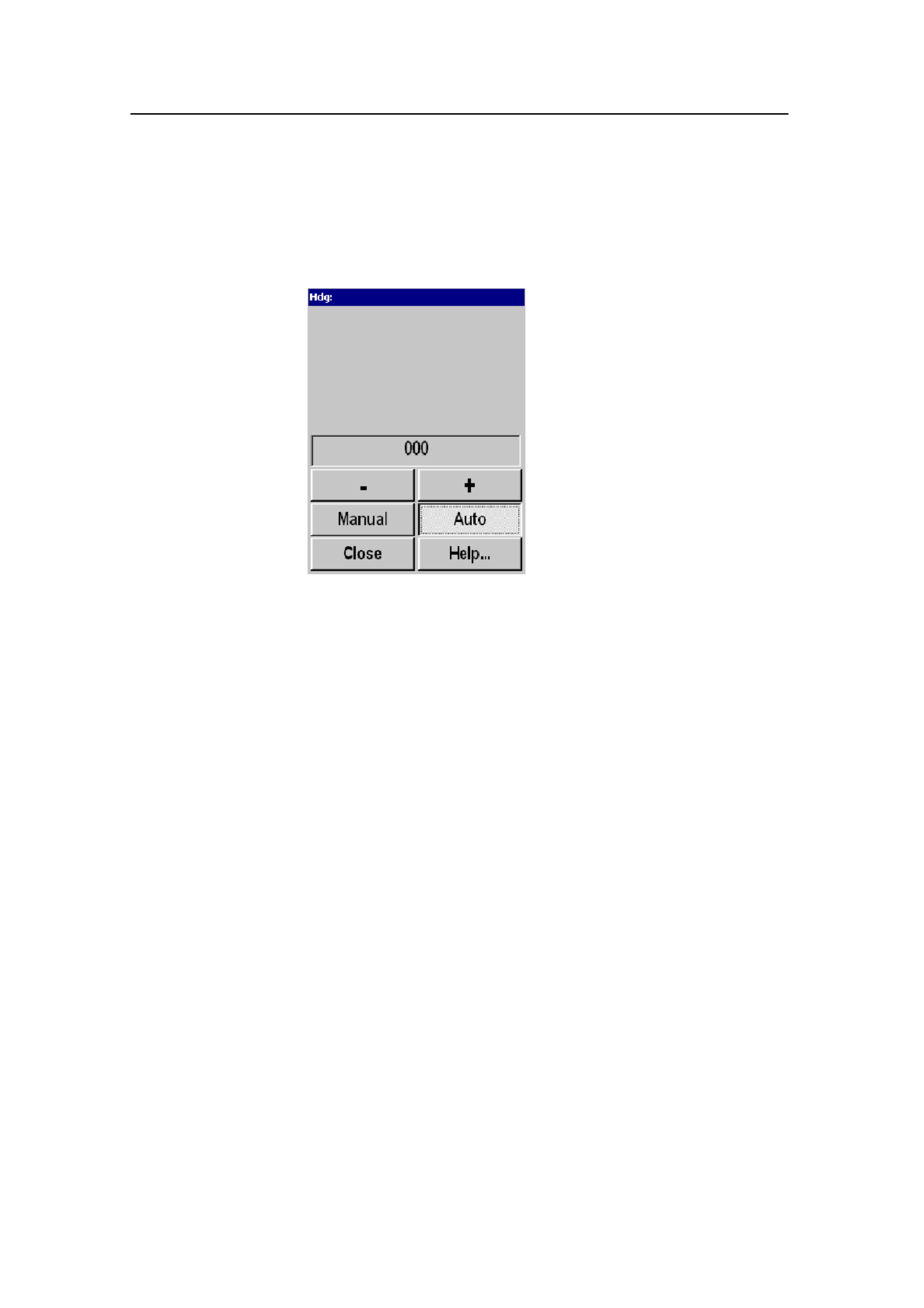
Heading
The Heading parameter is accessed by pressing the Hdg
(Heading) button in the Status dialogue at the bottom of the
menus.
The Heading readout is a repetition of the connected course
gyro input. Manual heading input may be used if signals from
external sensors are missing. By selecting Manual, the + and -
buttons can be used to alter the heading value.
Important: This readout must not be used for navigat ion.

Simrad SP60
110 850-164575 / Rev.D
Inspect Object
The Inspect Object parameters are either accessed when you
select a target marker in the Objects menu, or when you place
the cursor on the marker and pushes the Select button on the
Sonar Operating Panel.
The Inspect object parameter dialogue displays the current
parameters for the chosen object. Note that every parameter may
not be applicable for all marker categories.
The following parameters are shown:
- Depth
- Distance
- Bearing (B)
- Speed (S)
- Course (CO)
- Geographical position
- Area (A)
- Volume (V)
The Delete and Set Priority buttons allow you to remove an
object, or to change its status to “priority”.
Delete - This button allows you to delete the chosen target
Set p riority - This button sets the current target marker to the
“priority” marker. The marker is then identified with a “P”.
Related topics
→ Sonar Operating Panel; Select, page 30
Parameters
111
850-164575 / Rev.D
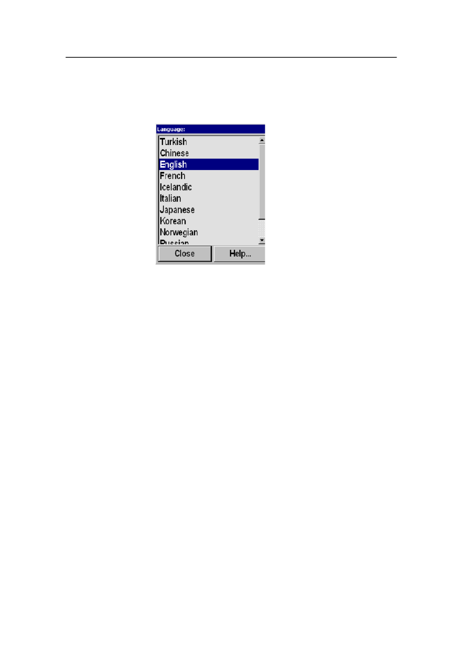
Language
The Language button is located on the Display menu.
The Language parameter dialogue is used to select the language
on the menus.

Simrad SP60
112 850-164575 / Rev.D
Menu
The Menu button is located in the Display menu.
The Menu parameter is used to select different levels of
complexity of the menu system.
• For simplified use, select the Short menu system. Only the
most important parameters will then be shown in the menus.
• For normal operation, select Normal. This setting is
recommended for most users after some experience with the
sonar.
• For advanced use, select Full. All parameters in the menus
will be shown.

Simrad SP60
114 850-164575 / Rev.D
Mode
The Mode button is located on the top of every menu.
The Mode parameter dialogue is used to select display mode. It
will automatically provide a selection between the modes
currently available on the sonar.
The various dipslay modes are described in the Display Modes
chapter.
The modes can also be selected with the four Mode buttons on
the Sonar Operating Panel. The various modes to activate using
those four buttons are controlled by the Sort Modes menu.
Related topics
→ Display Modes, page 13
→ Sort Modes menu, page 68
→ Sonar Operating Panel; Modes, page 27

Parameters
115
850-164575 / Rev.D
Mode Buttons
The Mode Buttons button is located in the Display menu.
This is simply a selector switch. Click on the button to select
Mode or User, and by this defining the operational function of
the four Mode buttons on the Sonar Operating Panel.
Mode Mode: The four buttons on the Sonar Operating Panel
can be used to select from your favourite modes.
User: The four Mode buttons on the Sonar Operating Panel can
be used to select between four favourite user settings.
Related topics
→ Sort Modes, page 68
→ User settings, page 148
→ Mode buttons, page 27

Simrad SP60
116 850-164575 / Rev.D
Movements
The Movements button is located in the menuSetup .
The Movements function makes it possible to estimate the
position of a tracked school at a given time (from one to ten
minutes). Estimate school position is presented by a violet dot.
When selecting 0, the movement estimation is switched Off.

Parameters
117
850-164575 / Rev.D
Palette
The Palette button is located in the Display menu.
The Palette parameter dialogue is used to select background
colours and day/night brightness of the display.

Parameters
119
850-164575 / Rev.D
PP Filter
The PP Filter can be accessed from the Horizontal and
Vertical menus.
The PP Filter (Ping-to Ping filter) reduces unwanted noise and
echoes from the screen. The filter has three different strengths.
As the ping-to-ping filter compares the echoes from the last 2
(Weak), 4 (Medium) or 8 (Strong) pings, it will take this
selected amounts of pings to make a stable presentation when
changing most of the sonar functions. The filtering routine takes
the vessel’s movements into consideration when comparing the
echoes from ping to ping.

Simrad SP60
120 850-164575 / Rev.D
Pulse Form
The Pulse Form is accessed from the Horizontal and Vertical
menus.
The Pulse Form parameter dialogue is used to select the form
of the transmitter pulse. This could either be CW (Continuous
Wave) with different pulse lengths, or FM (Frequency
Modulation) with different pulse lengths and number of
frequencies.
Range CW -- Pulse length (ms) FM
(meters) Short LongNormal Auto
150 0.9 1.8 5.3 FM4
300 1.8 3.5 10 FM4
450 2.7 5.3 15 FM4
600 3.5 7.1 20 FM4
900 5.3 10 30 FM4
1200 6.2 12 35 FM8
1500 7.1 15 45 FM8
2000 10 20 60 FM8
2500 12 25 75 FM8
3000 15 30 75 FM8
3500 18 35 75 FM8
4500 22 45 75 FM8
6000 30 60 75 FM8
8000 30 60 75 FM8
CW (Continuous Wave)
The frequency of the transmitter pulse is here constant, equal to
the selected frequency (if the optional multiple frequencies are
installed).

Parameters
121
850-164575 / Rev.D
There is a selection between three different pulse lengths:
Short, Normal and Long. In addition the pulse length will
change automatically in accordance with the selected range. The
table shows the different pulse lengths given in milliseconds
(ms).
FM (Frequency Modulation)
In the FM mode, the transmitter pulse is frequency modulated.
This provides a stable echo presentation and greater ability of
detection as noise and reverberation are reduced.
There is a selection between these different FM modes:
• FM AUTO - This selection will automatically choose the
optimal number of frequencies for the selected range.
• FM1 - Transmits one-frequency pulse with a total pulse
length of 1 ms.
• FM2 - Transmits two-frequency pulses with a total pulse
length of 4 ms.
• FM4 - Transmits four-frequency pulses with a total pulse
length of 16 ms.
• FM8 - Transmits eight-frequency pulses with a total pulse
length of 64 ms.
The selected number of frequencies are transmitted in one ping,
and the receiver undertakes a spectrum analysis to compare the
received echoes with the transmitter’s frequency code. This
provides a filtering effect, where only “own echoes” are
displayed, and noise and other echoes are reduced. The table on
the previous page shows the maximum FM mode for all ranges.

Simrad SP60
122 850-164575 / Rev.D
Range
The Range parameter can be accessed from the button in the
Horizontal and Vertical menus.
Horizontal and vertical range is normally selected using
the SP60 Sonar Operating Panel. You can also control
these settings directly on the Range button. The
available choices are listed in this dialogue.
The Range buttons are described in the Sonar
Operating Panel chapter.
Available ranges (in meters) are:
150, 300, 450, 600, 900, 1200, 1500, 2000, 2500, 3000,
3500, 4500, 6000 and 8000.
In addition to the readout on the menu, the current
horizontal range is normally displayed over the tilt
indicator in the upper, left-hand corner of the display.
The following options are available in the Range parameter
dialogue:
Manual - Allows you to change the range manually.
Auto - Enables automatic range selection during position- and
target tracking. This allows for optimal tracking.
To maintain a steady display during seine setting, the lower
automatic range is set to 450 meters. Changing the range or
pressing the Manual buttons will stop the automatic ranging
function.
The SP60 sonar is designed to work with various horizontal
range units such as meter, nautical mile, US survey feett or
yards. This choice can be made by pressing the Units button in
the Display menu.
Related topics
→ Sonar Operating Panel; Range, page 29

Parameters
123
850-164575 / Rev.D
Range (Catch View)
The Range (Catch View) button is located in the Catch View
menu.
The CatchView menu is activated by pressing the View button
on The Sonar Operating Panel (or the middle mouse button),
while the cursor is located in the Catch view, and then selecting
View menu Viewon the pop-up menu.
The Range in the CatchView may be selected manually or
automatically.
In Manual, the range scale can be selected from the list in the
dialogue.
In Auto, the CatchView range will automatically follow the
range selected in the Vertical view.
Related topics
→ Sonar Operating Panel; View, page 25
Produkt Specifikationer
| Mærke: | Simrad |
| Kategori: | Skibsradar |
| Model: | SP60 |
Har du brug for hjælp?
Hvis du har brug for hjælp til Simrad SP60 stil et spørgsmål nedenfor, og andre brugere vil svare dig
Skibsradar Simrad Manualer

8 Oktober 2024
8 Oktober 2024
3 Oktober 2024
4 September 2024
8 August 2024
6 August 2024
3 August 2024
8 Marts 2024
21 Januar 2023
18 December 2022
Skibsradar Manualer
- Skibsradar Lowrance
- Skibsradar Garmin
- Skibsradar Navman
- Skibsradar Raymarine
- Skibsradar Furuno
- Skibsradar JRC
Nyeste Skibsradar Manualer
5 September 2024
5 September 2024
23 August 2024
21 August 2024
21 August 2024
19 August 2024

18 August 2024
18 August 2024
17 August 2024
15 August 2024