Speco Technologies O5T2M Manual
Læs nedenfor 📖 manual på dansk for Speco Technologies O5T2M (60 sider) i kategorien sikkerhedskamera. Denne guide var nyttig for 12 personer og blev bedømt med 4.5 stjerner i gennemsnit af 2 brugere
Side 1/60

User Manual
5MP IP Camera
O5B2/ O5B2M/ O5D2/ O5D2M/ O5T2/ O5T2M/ O5P2
Please read this manual carefully before operating the unit keep it for further reference and

Important Safeguards and Warnings
1. Electrical safety
All installation and operation here should conform to local electrical safety codes.
Use a certified/listed 12VDC Class2 power supply only.
Please note: Do not connect two power supplying sources to the device at the same time; it may result in device damage! The
product must be grounded to reduce the risk of electric shock.
Improper handling and/or installation could run the risk of fire or electrical shock.
2. Environment
Heavy stress, violent vibration or exposure to water is not allowed during transportation, storage, and installation.
This product should be installed in a cool, dry place away from direct sunlight and heat sources.
Do not install the product in extreme temperature conditions.
Do not expose the camera to electromagnetic radiation. Otherwise, it may result in CMOS sensor failure.
Do not block any ventilation openings.
Do not allow water and liquid intrusion into the camera.
3. Operation and Daily Maintenance
Please shut down the device and then unplug the power cable before you begin any maintenance work.
Do not touch the CMOS sensor optic component. You can use a blower to clean the dust on the lens surface.
Always use the dry soft cloth to clean the device. If there is too much dust, use a cloth dampened with a small quantity of neutral
detergent. Finally use the dry cloth to clean the device.
Please use a professional optical cleaning method to clean the enclosure. Improper enclosure cleaning (such as using cloth) may
result in poor IR functionality and/or IR reflection.
The grounding holes of the product are recommended to be grounded to further enhance the reliability of the camera.
Dome cover is an optical device, please do not touch or wipe cover surface directly during installation and use, please refer to the
following methods if dirt is found.
Stained with dirt:
Use oil-free soft brush or hair dryer to remove it gently.
Stained with grease or fingerprint.
Use oil-free cotton cloth or paper soaked with alcohol or detergent to wipe from the lens center outward. Change the cloth and
wipe several times if it is not clean enough.

Warning
This camera should be installed by qualified personnel only.
All the examination and repair work should be done by qualified personnel.
Any unauthorized changes or modifications could void the warranty.
Statement
This guide is for reference only.
Product, manuals, and specifications may be modified without prior notice. Speco Technologies reserves the right to modify these
without notice and without incurring any obligation.
Speco Technologies is not liable for any loss caused by improper operation.
Regulatory Information
FCC conditions:
This device complies with part 15 of the FCC Rules. Operation is subject to the following two conditions:
⚫ This device may not cause harmful interference.
⚫ This device must accept any interference received, including interference that may cause undesired operation.
FCC compliance:
This equipment has been tested and found to comply with the limits for a digital device, pursuant to part 15 of the FCC Rules.
These limits are designed to provide reasonable protection against harmful interference. This equipment generates uses and can
radiate radio frequency energy and, if not installed and used in accordance with the instruction manual, may cause harmful
interference to radio communication. However, there is no guarantee that interference will not occur in a particular installation. If
this equipment does cause harmful interference to radio or television reception, which can be determined by turning the
equipment off and on, the user is encouraged to try to correct the interference by one or more of the following measures:
⚫ Reorient or relocate the receiving antenna.
⚫ Increase the separation between the equipment and receiver.
⚫ Connect the equipment into an outlet on a circuit different from that to which the receiver is connected.
Note:
Before installation, check the package and make sure that all components are included.
Contact your rep or Speco customer service department immediately if something is broken or missing in the package.
Accessory name
Amount
Network Camera Unit
1
Junction box
1
Quick Start Guide
1
Installation Accessories Bag
1
CD
1

Table of Contents
1 Introduction ............................................................................................................................................................................................................. 2
2 Web Access and Login .............................................................................................................................................................................................. 3
3 Live View 4 ..................................................................................................................................................................................................................
4 Camera Configuration 6 ..............................................................................................................................................................................................
4.1 System Configuration .............................................................................................................................................................. 6
4.1.1 System Information .................................................................................................................................................... 6
4.1.2 Date and Time ............................................................................................................................................................. 6
4.1.3 Local Recording ........................................................................................................................................................... 7
4.1.4 Storage ........................................................................................................................................................................ 7
4.2 Video Configuration ................................................................................................................................................................ 9
4.2.1 Image Configuration ................................................................................................................................................... 9
4.2.2 Video / Audio Configuration .....................................................................................................................................11
4.2.3 OSD Configuration ....................................................................................................................................................12
4.2.4 Video Mask ...............................................................................................................................................................12
4.2.5 ROI Configuration .....................................................................................................................................................13
4.2.6 Zoom/Focus ..............................................................................................................................................................14
4.3 Event Setup ...........................................................................................................................................................................14
4.3.1 Motion Detection .....................................................................................................................................................14
4.3.2 Other Alarms .............................................................................................................................................................16
4.3.3 Alarm In (Sensor Input) .............................................................................................................................................17
4.3.4 Alarm Out . ................................................................................................................................................................ 18
4.3.5 Alarm Server .............................................................................................................................................................19
4.4 Analytics Configuration .........................................................................................................................................................19
4.4.1 Exception ..................................................................................................................................................................19
4.4.2 Line Crossing .............................................................................................................................................................20
4.4.3 Intrusion ....................................................................................................................................................................22
4.4.4 Face Detection ..........................................................................................................................................................24
4.4.5 Region Entrance ........................................................................................................................................................25
4.4.6 Region Exiting ...........................................................................................................................................................26
4.4.7 Target Counting .........................................................................................................................................................28
4.5 Network Configuration .........................................................................................................................................................29
4.5.1 TCP/IP ........................................................................................................................................................................29
4.5.2 Port ...........................................................................................................................................................................30
4.5.3 Server Configuration .................................................................................................................................................31
4.5.4 Onvif..........................................................................................................................................................................31
4.5.5 DDNS .........................................................................................................................................................................31
4.5.6 SNMP ........................................................................................................................................................................32
4.5.7 802.1x .......................................................................................................................................................................33
4.5.8 RTSP ..........................................................................................................................................................................33
4.5.9 RTMP .........................................................................................................................................................................34
4.5.10 UPNP .........................................................................................................................................................................34
4.5.11 Email .........................................................................................................................................................................34
4.5.12 FTP ............................................................................................................................................................................35
4.5.13 HTTPS ........................................................................................................................................................................35
4.5.14 QoS ............................................................................................................................................................................36
4.6 Security Configuration ..........................................................................................................................................................37
4.6.1 User Admin ...............................................................................................................................................................37
4.6.2 Online User ...............................................................................................................................................................38

4.6.3 Block and Allow Lists .................................................................................................................................................38
4.6.4 Security Management ...............................................................................................................................................39
4.7 MaintenanceConfiguration ...................................................................................................................................................40
4.7.1 Backup and Restore ..................................................................................................................................................40
4.7.2 Reboot ......................................................................................................................................................................40
4.7.3 Upgrade ....................................................................................................................................................................40
4.7.4 Operation Log ...........................................................................................................................................................41
5 Search .................................................................................................................................................................................................................... 42
5.1 Image Search ........................................................................................................................................................................42
5.2 Video Search .........................................................................................................................................................................44
5.2.1 Local Video Search ....................................................................................................................................................44
5.2.2 SD Card Video Search................................................................................................................................................45
Appendix ........................................................................................................................................................................................................................ 48
Appendix 1 Troubleshooting ........................................................................................................................................................................................... 48
Appendix 2 Specifications ............................................................................................................................................................................................... 49
2
1 Introduction
Welcome
Thank you for purchasing this network camera!
Please read this manual carefully before operating the unit and retain it for further reference.
Should you require any technical assistance, please contact Speco Technologies Technical Support at 1-800-645-5516.
Main Features
⚫ Built-in PoE (Power over Ethernet)
⚫ Integrated IR LEDs for clear vision in low light
⚫ IP67 rated for outdoor installations
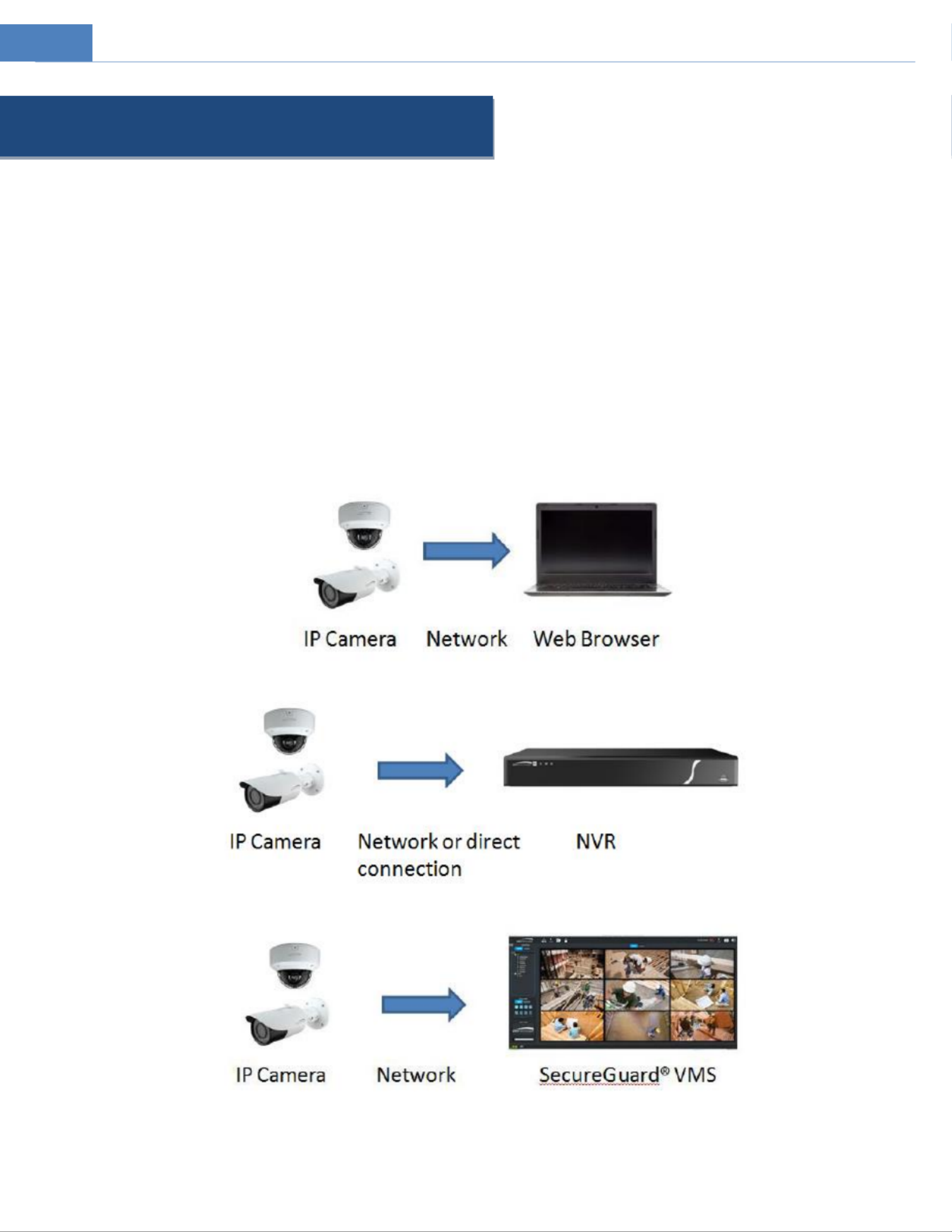
⚫ Remote viewing support via web browser, mobile APP, and CMS/VMS
Applications

3
2 Web Access and Login
The IP camera settings can be accessed via a web browser through the LAN.
Available web browser: IE (plug-in required)/ Firefox/Edge/Safari/Google Chrome
It is recommended to use the latest version of these web browsers.
The menu display and operation of the camera may be slightly different by using the browser with plug- or without plug-in. in
Installing plug-in will display more functions of the camera.
Connect IP-Cam via LAN or WAN. Here only take IE browser for example. The details are as follows:
⚫ Access through IP Scanner
Network connection:
①Make sure the PC and IP-Cam are connected on the same local network. The camera is set to DHCP by default and will be
assigned an IP address by the DHCP server. Make sure that the local network has a DHCP server. Routers typically have a DHCP server
built in.
② Install IP Scanner from the CD and run it after installation. IP Scanner is the tool for discovering the IP cameras on the local
network.
③ In the device list, the IP address, model number, and MAC address of each device will be listed. Select the applicable device and
double click to open up the web viewer. You can also manually enter the IP address in the address bar of the web browser. Read the
privacy statement and then check and click “Already Read to enter the login interface. ”
The login interface is shown above. Default username is and password is . After logging in, follow directions to install admin 1234
applicable plug-ins for viewing video if prompted.

4
3 Live View
The window below will be shown after logging in.
The following table describes the icons on the live view interface
Icon
Description
Icon
Description
Original size of resolution
SD card recording indicator
Fit (correct scale)
Abnormal color
indicator
Auto (fill the window)
Abnormal clarity indicator
Full screen (show video only)
Scene change indicator
Start/stop live view
Line crossing indicator
Start/stop two-way audio
Region entrance indicator
Enable/disable audio
Region exiting indicator
Snapshot
Line Crossing Target counting indicator
Start/stop local recording
Intrusion indicator
Zoom in (for motorized models)
Sensor alarm indicator
Zoom out (for motorized
models)
Motion alarm indicator
Zoom/Focus control (for
motorized models)
Face detection indicator
Rule information display
Face detection

5
*Plug-in free live view: PTZ control, two-way audio and local recording are not supported.
⚫ All indicator icons above will flash in live view interface only when the corresponding events are enabled.
⚫ In full screen mode, to exit, double click on the mouse or press the ESC key on the keyboard.
Click the zoom/focus control button to show the control panel. The descriptions of the control panel are as follows:
Icon
Description
Icon
Description
Zoom -
Zoom +
Focus -
Focus +
One key focus (used when image is out of focus after manual adjustment)
Face Capture View
① Go to Config→Event→Face Detection interface. Check “Enable”.
② Return to the live view interface. Click to go to the following interface. When there are faces detected, the face pictures
will be listed on the right.

6
4 Camera Configuration
Press the Setup button to go to the configuration interface. “ ”
Note: Wherever applicable, click the “Save” button to save the settings.
4.1 System Configuration
4.1.1 System Information
In the “System Information interface, the system information of the device is listed. ”
4.1.2 Date and Time
To set the time and date, go to System Date and Time. Please refer to the following interface. →
Select the applicable time zone and enable / disable DST as needed.
Click the “Date and Time” tab to set the time and date.

7
4.1.3 Local Recording
Go to System Local Recording to set up the storage path of captured pictures and recorded videos on the local PC There is also an →.
option to enable or disable the bitrate display in the recorded files.
Additionally, the snapshots triggered by smart events (including face detection, line crossing detection and intrusion detection) can
be selected to save to the local PC.
Rendering Mode: High-efficient mode, compatible mode or low-efficient mode can be optional.
If the performance of your computer is not compatible with the web client or your computer has no graphics card, low-efficient
mode is suggested.
4.1.4 Storage
Go to System Storage to go to the interface as shown below. →
⚫ SD Card Management
When the card is used for the first time, click the “Format” button to format the SD card. All data on the card will be cleared by
clicking this button.
Click the “Eject button to stop writing data to the SD card. Then the SD card can be ejected safely. ”
Snapshot Quota: Set the capacity proportion of captured pictures on the SD card.
Video Quota: Set the capacity proportion of record files the SD card. on
⚫ Schedule Recording Settings

8
1. Go to Storage Record to go to the interface as shown below. →
2. Set record stream, pre-record time cycle writing. and
Pre Record Time: Set the time to record before the actual recording begins.
3. Set schedule recording. Check “Enable Schedule Record” and set the schedule.
Week schedule ly
Set the alarm time from Monday to Sunday for a single week Each day is divided in one-hour increments. Green means scheduled. .
Blank means unscheduled.
“Add”: Add the schedule for a special day. Drag the mouse to set the time on the timeline.
“Erase”: Delete the schedule. Drag the mouse to erase the time on the timeline.
Manual Input: Click it for a specific day to enter specific start and end times. This adds more granularities (minutes).
Day schedule
Set the alarm time for alarm a special day, such as holiday. a
Note: Holiday schedule takes priority over w schedule. eekly
⚫ Snapshot Settings
Go to System Storage Snapshot to go to the interface as shown below. → →

9
Set the format, resolution and quality of the image saved the SD card and the snapshot interval and quantity the timing on and
snapshot here.
Snapshot Quantity: The number you set here is the maximum quantity of snapshots. The actual quantity of snapshots may be less
than this number. Supposing the occurrence time of an alarm event is less than the time capturing pictures, the actual quantity of of
snapshots is less than the set quantity of snapshots.
Timing Snapshot: Enable timing snapshot first and then set the snapshot interval and schedule. The setup steps of schedule are the
same as the schedule recording (See Schedule Recording).
4.2 Video Configuration
Video Configuration includes Image Settings, Video/Audio Setup, OSD, Privacy Mask and Region of Interest.
4.2.1 Image Configuration
In the Image Settings interface as shown below, various settings can be adjusted, such as brightness, contrast, hue, and saturation
and so on. The common mode and day and night mode can be set up separately. The image effect can be quickly viewed by
switching the configuration file.

10
Brightness: Set the brightness level of the camera’s image.
Contrast: Set the color difference between the brightest and darkest parts.
Hue: Set the total color degree of the image.
Saturation: Set the degree of color purity. The purer the color, the brighter the image is.
Sharpness: Set the resolution level of the image plane and the sharpness level of the image edge.
Noise Reduction: Decrease the noise and make the image more thorough. Increasing the value will make the noise reduction effect
better but it will reduce the image resolution.
Defog: Activating this function and setting an appropriate value as needed in foggy, dusty, oggy, or rainy environment to get clear sm
images.
Lens Distortion Correction: When the image appears distortion to some extent, please enable this function and adjust the level
according to the actual scene to correct the distortion.
Auto Iris: If your camera is auto Iris, please enable it.
Backlight Compensation (BLC):
⚫ Off: disables the backlight compensation function. It is the default mode.
⚫ WDR: WDR can adjust the camera to provide a better image when there are both very bright and very dark areas simultaneously
in the field of the view by lowering the brightness of the bright area and increasing the brightness of the dark area.
Recording will be stopped for a few seconds while the mode is changing from non-WDR to WDR mode.
⚫ HLC: lowers the brightness of the entire image by suppressing the brightness of the image’s bright area and reducing the size of
the halo area.
⚫ BLC: If enabled, the auto exposure will activate according to the scene so that the object of the image in the darkest area will be
seen clearly.
HFR: High Frame Rate. If is selected, the system will restart and then the maximum value of the frame rate of the main stream “ON”
can be set to 60 fps /50fps.
Antiflicker:
⚫ Off: disables the anti-flicker function. This is used mostly in outdoor installations.
⚫ 50Hz: reduces flicker in 50Hz lighting conditions.
⚫ 60Hz: reduces flicker in 60Hz lighting conditions.
Smart IR: Choose or OFF . This function can effectively avoid image overexposure and underexposure by controlling the “ON” “ ”
brightness of the IR lights according to the actual conditions to make the image more realistic. Please enable it as needed.
White Balance: Adjust the color temperature according to the environment automatically.
Frequency: 50Hz and 60Hz can be optional.
Day/Night Mode: Choose Auto , “ ” “ ” “Day , Night” “ or Timing”.
Gain Mode: Choose Auto or Manual . If Auto is selected, the gain value will be automatically adjusted according to the actual “ ” “ ” “ ”
situation. If Manual is selected, the gain value shall be set manually. The higher the value is, the brighter the image is. “ ”
Frequency: 50Hz and 60Hz can be optional.
Inf -red Mora de: Choose Auto , or OFF . “ ” “ON” “ ”
Exposure Mode: Choose “Auto” or “Manual”. If manual is chosen, the digital shutter speed can be adjusted.
Corridor Pattern: Corridor viewing modes can be used for situations such as long hallways. 0, 90, 180 and 270 are available. The
default value is 0. The video resolution should be 1080P or below if this function is used.
Image Mirror: Turn the current video image horizontally.
Image Flip: Turn the current video image vertically.
Schedule Settings of Image Parameters:
Click the “Profile Management” tab as shown below.
Set full time schedule for common, day or Timingnight mode and specified time schedule for day and night. Choose “ ” in the

11
drop-down box of schedule as shown below.
Drag “ ” icons to set the time of day and night. Blue means daytime and blank means night time. If the current mode of camera
parameters is set to Timing , the image configuration mode will automatically switch between day and night according to the “ ”
schedule.
4.2.2 Video / Audio Configuration
Go to Image Video / Audio interface as shown below. In this interface, set the resolution, frame rate, bitrate type, video quality →
and so on subject to the actual network condition.
Click the “Audio” tab to go to the interface as shown below.
Three video streams can be adjustable.
Resolution: The size of image.
Frame rate: The higher the frame rate, the video is smoother.
Bitrate type: CBR and VBR are optional Bitrate is related to image quality. CBR means that no matter how much change is seen in .
the video scene, the compression bitrate will be kept constant. VBR means that the compression bitrate will be adjusted according to
scene changes For example, for scenes that do not have much movement, the bitrate will be kept at a lower value. This can help .
optimize the network width usage. band
Bitrate: it can be adjusted when the mode is set to CBR. The higher the bitrate, the better the image quality will be.
Video Quality: It can be adjusted when the mode is set to VBR. The higher the image quality, the more bitrate will be required.
I Frame interval: It determines how many frames are allowed between a “group of pictures”. When a new scene begins in a video,
until that scene ends, the entire group of frames (or pictures) can be considered as a group of pictures. If there is not much
movement in the scene, setting the value higher than the frame rate is fine, potentially resulting in less bandwidth usage. However, if

12
the value is set too high, and there is a high frequency of movement in the video, there is a risk of frame skipping.
Video Compression: MJPEG, H264+, H264, H265 or H265+ can be optional. MJPEG is not available for main stream. If H.265/H.265+/
H.265S is chosen, make sure the client system is able to decode H.265/H.265+. Compared to H.265, H.265+ saves more storage space
with the same maximum bitrate in most scenes. Compared to H.264, H.265 reduces the transmission bitrate under the same
resolution, frame rate and image quality.
Profile: For H.264. Baseline, main and high profiles are selectable.
Send Snapshot: Set the snapshot stream.
Video encode slice split: I this function is enabled, smooth image can be gotten even though using the low-performance PC. f
Watermark: When playing back the local recorded video in the search interface, the watermark can be displayed. To enable it, check
the watermark box and enter the watermark text.
Audio Encoding: G711A and G711U are selectable.
Audio Type: LIN. Some models may support MIC type.
4.2.3 OSD Configuration
Go toVideo OSDinterface as shown below. →
Set time stamp, device name, OSD content and picture overlap here. After enabling the corresponding display and entering the
content, drag them to change their position. Then click the “Save” button to save the settings.
Picture Overlap Settings:
Check “OSD Content1”, choose “Picture Overlay” and click “Browse” to select the overlap picture. Then click “Upload” to upload the
overlap picture. The pixel of the image shall not exceed 200*200, or it cannot be uploaded.
4.2.4 Video Mask
Go to Image→Video Mask interface as shown below. A maximum of 4 zones can be set up.

13
To set up video mask:
1. Enable video mask.
2. Click the “Draw Area” button and then drag the mouse to draw the video mask area.
3. Click the “Save” button to save the settings.
4. Return to the live to verify that the area have been drawn as shown as blocked out in the image.
To clear the video mask:
C the lick “Clear” button to delete the current video mask area.
4.2.5 ROI Configuration
Go to Image ROI Config interface as shown below. An area in the image can be set as a region of interest. This area will have a →
higher bitrate than the rest of the image, resulting in better image quality for the identified area.

14
1. Check “Enable” and then click “Draw Area” button.the
2. Drag the mouse to set the ROI area.
3. Set the level.
4. Click the “Save” button to save the settings.
4.2.6 Zoom/Focus
This function is only available for the model with motorized zoom lens. Within this section, zoom and focus can be controlled. If
the image is out of focus after a manual adjustment, one key focus can be used to set the focus automatically.
4.3 Event Setup
4.3.1 Motion Detection
Go to Alarm Motion Detection to set motion detection alarm. →

15
1. Check “Enable” check box to activate motion-based alarms. If unchecked, the camera will not send out any signals to trigger
motion-based recording to the NVR or CMS, even if there is motion in the video.
Alarm Out: If selected, this would trigger an external relay output that is connected to the camera on detecting a motion-based
alarm.
Trigger SD Snap: If selected, the system will capture images on motion detection and save the images on an SD card.
Trigger SD Recording: If selected, video will be recorded on an SD card on motion detection.
Trigger Email: If “Trigger E ”mail and “Attach Picture are checked (email address must be set first in the ail configuration ”Em
interface), the captured pictures and triggered event will be sent into those addresses.
Trigger FTP: If “Trigger FTP” and “Attach Picture” are checked, the captured pictures will be sent into FTP server address. Please
refer to FTP configuration chapter for more details.
2. Set motion detection area and sensitivity. Click the “Area and Sensitivity” tab to go to the interface as shown below .
Move the “Sensitivity” scroll bar to set the sensitivity. Higher sensitivity value means that motion will be triggered more easily.
Select “Add” and click “Draw”. Drag the mouse to draw the motion detection area; Select “Erase” and drag the mouse to clear
motion detection area.
After that, click the “Save” to save the settings.“Clear All” can be used to clear out the entire motion zone.
3. Set the schedule for motion detection. The schedule setup steps of the motion detection are the same as the schedule recording
setup (See Schedule Recording).

16
4.3.2 Other Alarms
⚫ SD Card Full
1. Go to Alarm→Anomaly→SD Card Full.
2. Enable and set the alarm holding time. Click “ ”
3. Set alarm trigger options. The setup steps are the same motion detection. Please refer to motion detection chapter for details. as
⚫ SD Card Error
When there are some errors in writing SD card, the corresponding alarms will be triggered.
1. Go to Alarm→Anomaly→SD Card Error as shown below.
2. Click “Enable” and set the alarm holding time.
3. Set alarm trigger options. Trigger alarm out, Email and FTP. The setup steps are the same motion detection. Please refer to as
motion detection chapter for details.
⚫ IP Address Conflict
This function is only available for the models with Alarm Out interface.
1. Go to Alarm→Anomaly→IP Address Collision as shown below.

17
2. Click “Enable” and set the alarm holding time.
3. Trigger alarm out. When the IP address of the camera conflicts with the IP address of other devices, the system will trigger the
alarm out.
⚫ Cable Disconnection
This function is only available for the models with Alarm Out interface.
1. Go to Alarm→ →Anomaly Cable Disconnected as shown below.
2. Click “Enable” and set the alarm holding time.
3. Trigger alarm out. When the camera is disconnected, the system will trigger the alarm out.
4.3.3 Alarm In (Sensor Input)
This function is only available for some models. To set sensor alarm (alarm in):
Go to Alarm Alarm In interface as shown below. →

18
1. nable and set the alarm type, alarm holding time and sensor name. Click “E ”
2. Set alarm trigger options. The set steps are the same as motion detection. Please refer to up motion detection chapter for details.
3. Click “Save” button to save the settings.
4. Set the schedule of the sensor alarm. The set steps of the schedule are the same the schedule recording setup. (See up as
Schedule Recording).
4.3.4 Alarm Out
This function is only available for some models. Go to Alarm Alarm Out. →
Alarm Out Mode: Alarm linkage, manual operation, day/night switch linkage and schedule are optional.
Alarm Linkage: Having selected this mode, select alarm out name, alarm holding time at the “Alarm Holding Time” pull down list box
and alarm type.
Manual Operation: Having selected this mode, select alarm type and click “Open” to trigger the alarm out immediat click “Close” ely;
to stop alarm.
Day/Night Switch Linkage: Having selected this mode, select the alarm type and choose to open or close alarm out when the
camera switches to day mode or night mode.
Timing: Select the alarm type. Then click “Add” and drag the mouse on the timeline to set the schedule of alarm out; click “Erase”
and drag the mouse on the timeline to erase the set time schedule. After this schedule is saved, the alarm out will be triggered in the
specified time.

19
4.3.5 Alarm Server
Go to Alarm Alarm Server interface as shown below. →
Set the server address, port, heartbeat, and heartbeat interval. When an alarm occurs, the camera will transfer the alarm event to
the alarm server. If an alarm server is not needed, there is no need to configure this section.
4.4 Analytics Configuration
This series of IP cameras supports certain smart functions, such as line crossing detection, region intrusion detection, etc. These
events can be triggered as alarm events.
For more accuracy, here are some recommendations for installation.
⚫ Cameras should be installed on stable surfaces as vibrations can affect the accuracy of detection. ,
⚫ Avoid pointing the camera at the reflective surfaces (like shiny floors, mirrors, glass, lake surfaces and so on).
⚫ Avoid places that are narrow or have too much shadowing.
⚫ Avoid scenario where the object color is similar to the background color. ’s
⚫ At any time of day or night, please make sure the image of the camera is clear and with adequate and even light, avoiding
overexposure or too much darkness on both sides.
⚫ Ensure that the specific analytic enabled meet the minimum requirements for percentage of screen and/or distance.
4.4.1 Exception
This function can detect changes in the surveillance environment affected by the external factors.
Go to Event Exception interface as shown below. →

21
1. Enable line crossing alarm and select the snapshot type and the detection target.
Save Panoramic Picture: If it is enabled, the detected panoramic pictures will be captured and saved to the SD card when there are
targets detected.
Save Target Cutout: If it is enabled, the detected target cutout pictures will be captured and saved to the SD card when there are
targets detected.
Note: To save images to a local PC, please enable the local smart snapshot storage first (System Local Recording). To save images to →
an SD card, please install an SD card first.
Detection Target:
Human: Select it and then alarms will be triggered if someone crosses the pre-defined alarm line.
Motor Vehicle: Select it and then alarms will be triggered if a vehicle with four or more wheels (eg. a car, bus or truck) crosses the
pre-defined alarm line.
Non-motor Vehicle: Select it and then alarms will be triggered if a vehicle with two wheels (eg. a motorcycle or bicycle) crosses the
pre-defined alarm line.
All of the three types of objects can be selected simultaneously. Please select the detection objects as needed. If no object/target is
selected, alarms will not be triggered even if line crossing detection is enabled.
2. Set the alarm holding time.
3. Set alarm trigger options. The setup steps are the same motion detection. Please refer to as motion detection chapter for details.
4. Click “Save” button to save the settings.
5. Set area and sensitivity of the line crossing alarm. Click the “Area and Sensitivity” tab to go to the interface as shown below.

22
Set the alarm line number and direction. Up to 4 lines can be added. Multiple lines cannot be added simultaneously.
Direction:A<->B, A->B and A<-B optional. This indicates the direction of the intruder who crosses over the alarm line that would
trigger the alarm .
A<->B: The alarm will be triggered when the intruder crosses over the alarm line from B to A or from A to B.
A->B: The alarm will be triggered when the intruder crosses over the alarm line from A to B.
A<-B: The alarm will be triggered when the intruder crosses over the alarm line from B to A.
Click the “Draw Area” button and then drag the mouse to draw a in the image. line Click the “ ” button to stop drawing. Stop Draw
Click the “Clear” button to delete the line Click the “Save” button to save the settings. s.
6. Set the schedule of the line crossing alarm. The setup steps of the schedule are the same the schedule recording setup (See as
Schedule Recording).
※Configuration of camera and surrounding area
1. Auto-focusing function should not be enabled for line crossing detection.
2. Avoid the scenes with many trees or the scenes with various light changes (like many flashing headlights). The ambient brightness
of the scenes shouldn’t be too low.
3. Cameras should be mounted at a height of 10ft or above.
4. Keep the mounting angle of the camera at about 45°.
5. The detected objects should not be less than 1% of the entire image and the largest sizes of the detected objects should not be
more than 1/8 of the entire image. This analytic relies on the percentage of the detected objects relative to the entire image and
not distance.
6. Make sure cameras can view objects for at least 2 seconds in the detected area for accurate detection.
7. Adequate light and clear scenery are crucial for line crossing detection.
4.4.3 Intrusion
Intrusion: Alarms will be triggered if the target intrudes into the defined areas.
Go to Event Intrusion interface as shown below. →

24
4.4.4 Face Detection
Face detection function is to detect the face appearing in the surveillance scene. Alarms will be triggered when a face is detected.
The setting steps are as follows:
1. Go to Event→Face Detection as shown below.
2. Enable the face detection function.
Save Source Information: if checked, the whole picture will be saved to an SD card when detecting a face.
Save Face Information: if checked, the captured face picture will be saved to an SD card when detecting a face.
Note: To save images to a local PC, please enable the local smart snapshot storage first (System Local Recording). To save images to →
an SD card, please install an SD card first.
3. Set alarm holding time and alarm trigger options. The alarm trigger setup steps are the same as motion detection setup. Please
refer to motion detection chapter for details.
4. Set alarm detection area.
Use this to draw the approximate size of the face that you want the camera to capture. This is useful when there are multiple faces

25
in the background or foreground that are not needed to be captured. To enable, Click “Draw Area” and drag the border lines of the
rectangle to modify its size. Move the rectangle to change its position. Click “Stop Draw” to stop drawing the area. Click “Clear” to
clear the area. Then set the detectable face size by defining the maximum value and the minimum value(The default size range of a
single face image occupies from 3% to 50% of the entire image). This analytic relies on the percentage of the face to the entire
image as well as distance.
5. Set the schedule of the face detection. The setup steps of the schedule are the same as schedule recording setup (See Schedule
Recording).
6. Advanced configuration. Choose the snapshot interval and number as needed to avoid capturing multiple similar pictures in a very
short period of time.
Snapshot Interval: If 5 seconds is selected, the camera will capture the same target once every 5 seconds during its continuous tracking period.
Snapshot Number: If the snapshot number is enabled and set (eg. 3), the camera will capture the same target once every 5 seconds and it will capture this
target 3 times at most during its continuous tracking period. If the snapshot number is disabled, the camera will capture the same target once every 5
seconds until the target disappears in the detected area.
※ Configuration requirements of camera and surrounding area
1. Cameras must be installed in the area with stable and equate light sources. ad
2. The installation height ranges from 1.9m(6.2ft) to 2.5m(8.2ft), adjustable according to the focal-length of different lenses and
object distances.
3. The depression angle (a) of the camera shall be less than or equal to 15°.
4. The object distance depends on the focal-length of the lens mounted in the camera.
5. In order to guarantee the captured face recognition rate, the requirement for face capture are: left or right face turn angle is less
than about 30°; pitching angle is less than 20°.
6 Face illumination must be uniform, if the brightness is low or there is a large area of shadow, need to do the light filling. .
7. When the capture scenario is backlight, the camera’s BLC/HLC/WDR need to be turned on, or fill the light.
8. The face recognition do not support black & white mode for now.
4.4.5 Region Entrance
Region Entrance: Alarms will be triggered if the target enters the pre-defined areas.
Go to Config Event Region Entrance interface as shown below. → →

26
1. Enable region entrance detection and select the snapshot type and the detection target.
2. Set the alarm holding time.
3. Set alarm trigger options. The setup steps are the same as motion detection. Please refer to motion detection chapter for details.
4. Click the “Save” button to save the settings.
5. Set the alarm area of the region entrance detection. Click the “Area” tab to go to the interface as shown below.
Set the alarm area number on the right side. Up to 4 alarm areas can be added.
Click the “Draw Area” button and then click around the area where you want to set as the alarm area in the image on the left side
(the alarm area should be a closed area). Click the “Stop Draw” button to stop drawing. Click the “Clear” button to delete the alarm
area. Click the “Save” button to save the settings.
6. Set the schedule of the region entrance detection. The setup steps of the schedule are the same as schedule recording setup (See
Schedule Recording).
* The configuration requirements of camera and surrounding area are the same as intrusion detection.
4.4.6 Region Exiting
Region Exiting: Alarms will be triggered if the target exits from the pre-defined areas.

27
Go to Config Event Region Exiting interface as shown below. → →
1. Enable region exiting detection and select the snapshot type and the detection target.
2. Set the alarm holding time.
3. Set alarm trigger options. The setup steps are the same as motion detection. Please refer to motion detection chapter for details.
4. Click the “Save” button to save the settings.
5. Set the alarm area of the region exiting detection. Click the “Area” tab to go to the interface as shown below.
Set the alarm area number on the right side. Up to 4 alarm areas can be added.
Click the “Draw Area” button and then click around the area where you want to set as the alarm area in the image on the left side
(the alarm area should be a closed area). Click the “Stop Draw” button to stop drawing. Click the “Clear” button to delete the alarm
area. Click the “Save” button to save the settings.
6. Set the schedule of the region exiting detection. The setup steps of the schedule are the same as schedule recording setup (See
Schedule Recording).
* The configuration requirements of camera and surrounding area are the same as intrusion detection

28
4.4.7 Target Counting
This function is to calculate the number of the people or vehicles crossing the alarm line through detecting, tracking and counting
the shapes of the people or vehicles.
1. Go to Config Event Target Counting as shown below. → →
2. Enable target counting and select the snapshot type and the detection target.
Detection Target: Select the target to calculate. Human, motor vehicle and motorcycle/bicycle can be selected.
Staying Threshold: When the targets (human/vehicle) staying in the specified area exceed the threshold, alarms will be triggered.
Counting Reset: The current number of the target counting can be reset. You can choose to reset the counting daily, weekly or
monthly. Click “Reset” to manually reset the current number of crossing line people/car/bike counting.
3. Set the area of the target counting. Click the “Area” tab to go to the interface as shown below.

29
Set the alarm line number and direction. Only one alarm line can be added.
Direction:A->B and A<-B can be optional. The direction of the arrow is entrance.
Statistics: If enabled, you can see the statistical information in the live view interface. If disabled, the statistical information will not
be displayed in the live view interface.
The statistical OSD information can be customized as needed.
Click the “Draw Area” button and then drag the mouse to draw a line in the image. Check “Statistics” and then move the red box to
change the position of the statistical information displayed on the screen. Click the “Stop Draw” button to stop drawing. Click the
“Clear” button to delete the lines.
4. Set the schedule of the target counting. The setup steps of the schedule are the same as schedule recording setup (See Schedule
Recording).
5. View the statistical information in the live view interface.
4.5 Network Configuration
4.5.1 TCP/IP
Go to Network→TCP/IP interface as shown below. There are two ways for network connection.

30
Use IP address (take IPv4 for example)-obtain a local IP address automatically through DHCP. A typical router has a DHCP server
built in, and therefore is able to assign an IP address to the camera.
Use PPPoE-Click the “PPPoE Config” tab to go to the interface as shown below. Enable PPPoE and then enter the user name and
password from your ISP.
Either method of network connection can be used. If PPPoE is used to connect internet, the camera will get a dynamic WAN IP
address. This IP address will change frequently. To be notified, the IP change notification function can be used.
Click “IP Change Notification Config” to go to the interface as shown below.
Trigger Email: when the IP address of the device is changed, the new IP address will be sent to the email address that has been set
up.
Trigger FTP: when the IP address of the device is changed, the new IP address will be sent to FTP server that has been set up.
4.5.2 Port
Go toNetwork Port interface as shown below. HTTP port, Data port and RTSP port can be set. →
HTTP Port: The default HTTP port is 80. It can be changed to any port which is not occupied.
HTTPS Port: The default HTTPs port is 443. It can be changed to any port which is not occupied.
Data Port: The default data port is 9008. Please change it as necessary.
RTSP Port: The default port is 554. Please change it as necessary.
Persistent Connection Port: The port is used for a persistent connection of the third-party platform to push smart data, like face
pictures.
WebSocket Port: Communication protocol port for plug-in free preview.

31
4.5.3 Server Configuration
This function is mainly used for connecting network video management system.
1. Check “Enable”.
2. Check the IP address and port of the transfer media server in the VMS. Then enable the auto report in the VMS when adding a
new device. Next, enter the remaining information of the device in the VMS. After that, the system will automatically allot a device
ID. Please check it in the VMS.
3. Enter the above-mentioned server address, server port and device ID in the corresponding boxes. Click the “Save” button to save
the settings.
4.5.4 Onvif
The camera can be searched and connected to the third-party platform via ONVIF/RTSP protocol.
Note: when adding the device to the third-party platform with ONVIF/RTSP protocol, please enter the username and password
created in the above interface.
4.5.5 DDNS
If the camera is set up with a DHCP connection, DDNS should be set for accessing the camera from e internet. th
1. Go to Network DDNS. →
2. Enable, save and use DDNS to log in.

32
4.5.6 SNMP
To get camera status, parameters and alarm information and remotely manage the camera, the SNMP function can be used. Before
using SNMP, please install an SNMP management tool and set the parameters of the SNMP, such as SNMP port, trap address.
1. Go to Network SNMP. →
2. Check the corresponding version checkbox (Enable SNMPv1, Enable SNMPv2, Enable SNMPv3) according to the version of the
SNMP software that will be used.
3. Set the values for “Read SNMP Community”, “Write SNMP Community”, “Trap Address”, “Trap Port” and so on. Please make sure
the settings are the same as that of the SNMP software.

33
4.5.7 802.1x
If it is enabled, the camera s data can be protected. When the camera is connected to the network protected by the IEE802.1x, user ’
authentication is needed.
To use this function, the camera shall be connected to a switch supporting 802.1x protocol. The switch can be reckoned as an
authentication system to identify the device in local network. If the camera connected to the network interface of the switch has a
passed the authentication of the switch, it can be accessed via the local network.
Protocol type and EAPOL version: Please use the default settings.
User name and password: The user name and password must be the same with the user name and password applied for and
registered in the authentication server.
4.5.8 RTSP
Go toNetwork RTSP. →
Select “Enable” to enable the RTSP function.
Port: Access port of the streaming media. The default number is 554.
RTSP Address: The RTSP address (unicast) format that can be used to play the stream a media player. in
Multicast Address
Main stream: The address format is
“rtsp://IP address: rtsp port/profile1?transportmode=mcast”.
Sub stream: The address format is
“rtsp://IP address: rtsp port/profile2?transportmode=mcast”.
Third stream: The address format is
“rtsp://IP address: rtsp port/profile3?transportmode=mcast”.
Audio: Having entered the main/sub stream in media player(like VLC), the video and audio will play automatically. a
If llow a“A nonymous login…” is checked, there is no need to enter the username and password to view the video.
If “auto start” is enabled, the multicast received data should be added into a VLC player to play the video.

34
4.5.9 RTMP
You can access the third-party (like YouTube) to realize video live view through RTMP protocol.
Go to Config→Network RTMP. →
Check Enable“ ”, select stream type, set the reconnection time after timeout and server address as needed.
Server address: Enter the server address allocated by the third party server.
After that, click Save to save the settings. Then click Refresh to view the connection status. “ ” “ ”
4.5.10 UPNP
If this function is enabled, the camera can be quickly accessed through t LAN. he
Go to Network→UPnP. Enable UPNP and then enter UPnP name.
4.5.11 ail Em
If you need to trigger Email when an alarm happens or IP address is changed, please set the Email here first.
Go to Network→Email.
Sender Address: sender’s e-mail address.
User name and password: sender’s user name and password (you don’t have to enter the username and password if “Anonymous
Login” is enabled).
Server Address: The SMTP IP address or host name.

35
Select the secure connection type at the “Secure Connection” pull-down list according to what’s required.
SMTP Port: The SMTP port.
Send Interval(S): The time interval of sending email. For example, if it is set to 60 seconds and multiple motion detection alarms are
triggered within 60 seconds, they will be considered as only one alarm event and only one email will be sent. If one motion alarm
event is triggered and then another motion detection alarm event is triggered after 60 seconds,two emails will be sent. When
different alarms are triggered at the same time, multiple emails will be sent separately.
Click the “Test” button to test the connection of the account.
Recipient Address: receiver’s e-mail address.
4.5.12 FTP
After FTP server is set up, captured pictures from events will be uploaded to the FTP server. an
Go to Network→FTP.
Server Name: The name of the FTP server.
Server Address: The IP address or domain name of the FTP.
Upload Path: The directory where files will be uploaded to.
Port: The port of the FTP server.
Use Name and Password: The username and password that are used to login to the FTP server.
4.5.13 HTTPS
HTTPs provides authentication of the web site and protects user privacy.
Go to Network→HTTPS as shown below.
There is a certificate installed by default as shown above. Enable this function and save it. Then the camera can be accessed by
entering https://IP: https port via the web browser (eg. https://192.168.226.201:443).
A private certificate can be created if users don’t want to use the default one. Click “Delete” to cancel the default certificate. Then

36
the following interface will be displayed.
* If there is a signed certificate, click “Browse” to select it and then click “Install” to install it.
* Click “Create a private certificate” to enter the following creation interface.
Click the “Create” button to create a private certificate. Enter the country (only two letters available), domain (camera’s IP
address/domain), validity date, password, province/state, region and so on. Then click “OK” to save the settings.
* Click “Create a certificate request” to enter the following interface.
Click “Create” to create the certificate request. Then download the certificate request and submit it to the trusted certificate
authority for signature. After receiving the signed certificate, import the certificate to the device.
4.5.14 QoS
QoS (Quality of Service) function is used to provide different quality of services for different network applications. With the deficient
bandwidth, the router or switch will sort the data streams transfer them according to their priority to solve the network delay and
and network congestion by using this function.
Go to Network→QoS.
Video/Audio DSCP: The range is from 0 to 63.
Alarm DSCP: The range is from 0 to 63.
37
Manager DSCP: The range is from 0 to 63.
Generally speaking, the larger the number is, the higher the priority is.
4.6 Security Configuration
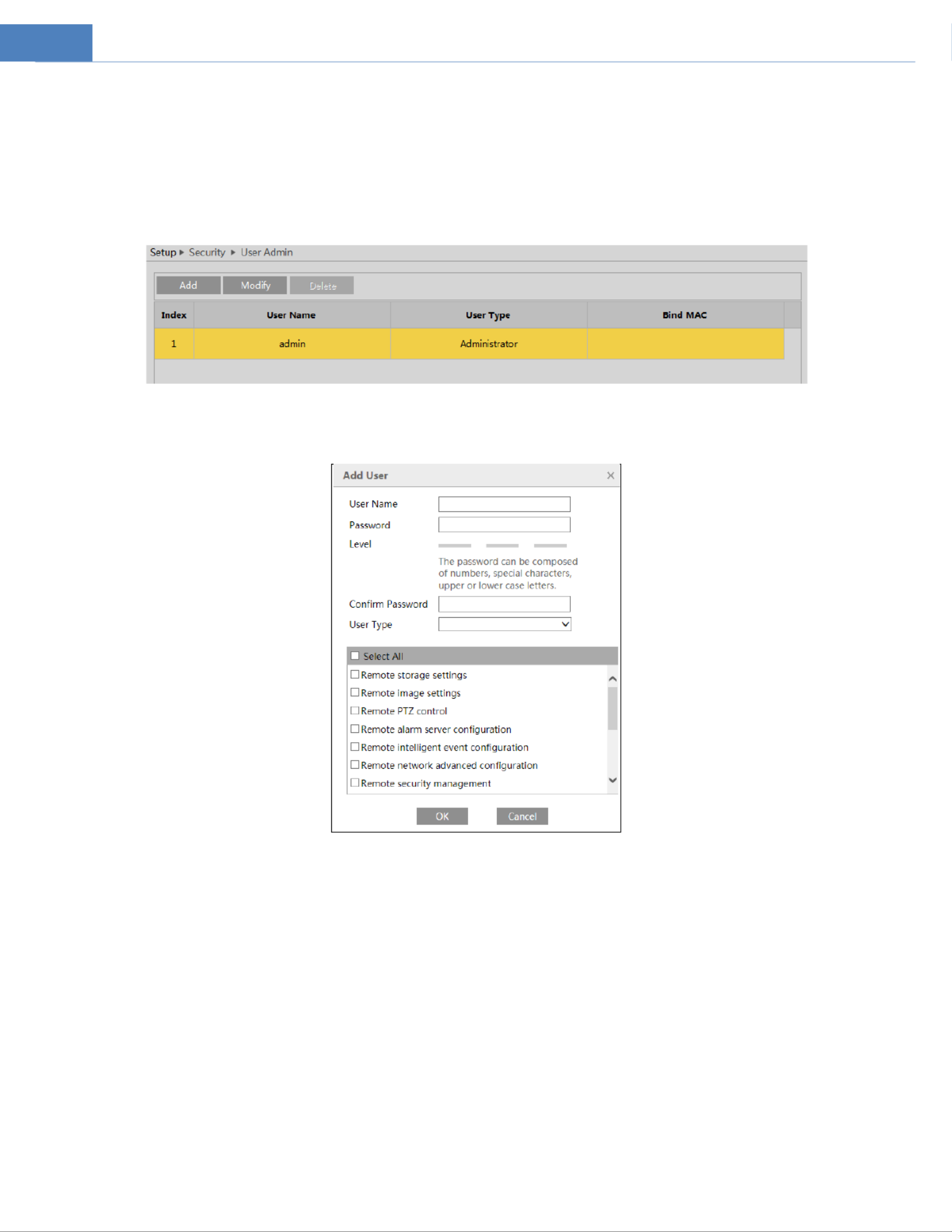
4.6.1 User Admin
Go to Security User Admin interface as shown below. →
Add user:
1. Click “Add” to pop up the following textbox.
2. Enter user name in “User Name” textbox.
3. Enter letters or numbers in “Password” and “Confirm Password” textbox. Please set the password according to the requirement of
the password security level (Go to Setup Security Security Management Password Security interface to set the security level). → → →
4. Choose the user type and select the permission.
6. Click the “OK” button and then the newly added user will be displayed in the user list.
Modify user:
1. Select a user to modify password and MAC address if necessary in the user configuration list box.
2. The “Edit user” dialog box pops up by clicking the “Modify” button.

38
3. Enter the old password of the user in the “Old Password” text box.
4. Enter the new password in the “New password” and “Confirm Password” text box.
5. Modify the permission as necessary.
6. Click the “OK” button to save the settings.
Note: To change the access level of a user, the user must be deleted and added again with the new access level.
Delete user:
1. Select the user to be deleted in the user configuration list box.
2. Click the “Delete” button to delete the user.
Note: The default administrator account ot be deleted. cann
4.6.2 Online User
Go to Security Online User to view the user who is viewing the live video. →
An administrator user can kick out all the other users (including other administrators).
4.6.3 Block and Allow Lists
Go to Security Block and Allow Lists as shown below. →
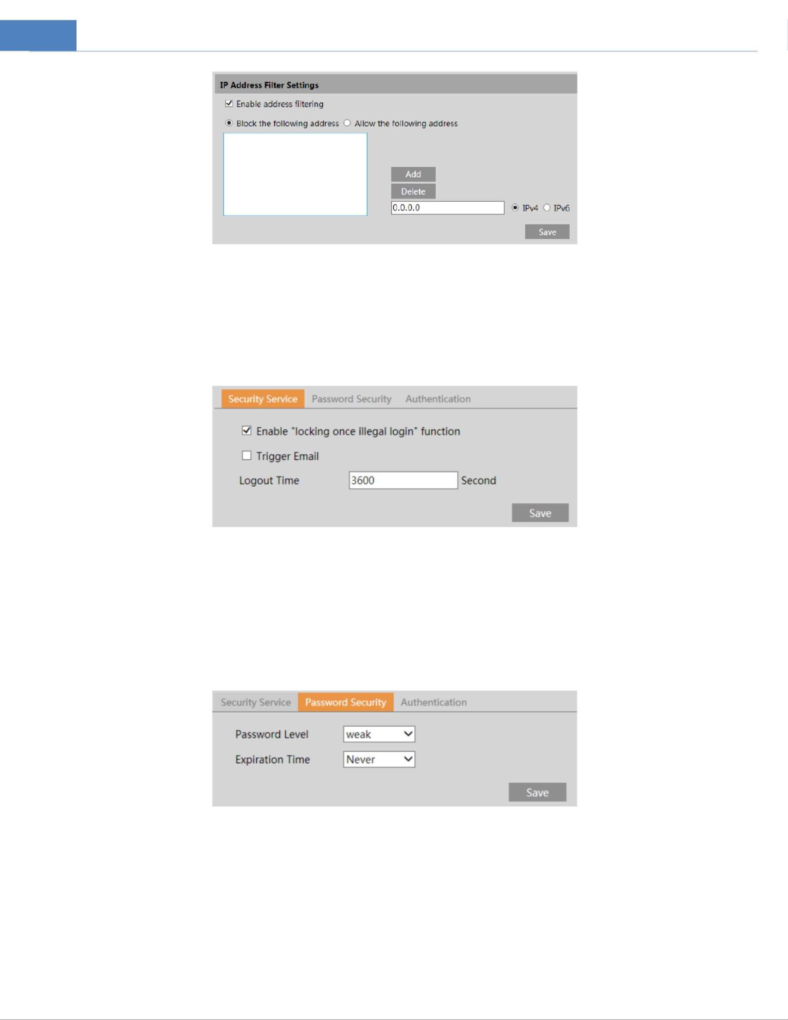
39
The setup steps are as follows:
Check the “Enable address filtering” check box.
Select “Block/Allow the following address”, IPv4/IPv6 and then enter address in the address box and cIP lick the “Add” button.
4.6.4 Security Management
Go to Security Security Management as shown below. →
In order to prevent against malicious password unlocking, “locking once illegal login” function can be enabled here. If this function is
enabled, login failure after trying six times will make the login interface locked. The camera can be logged in again after a half hour
or after the camera reboots.
Trigger Email: if enabled, e-mail will be sent when logging in/out or illegal login lock occurs.
Logout time: Set the logout time as needed. For example: 3600s, you will be automatically logged out after 3600s and then you
need to enter the username and password again to log in.
⚫ Password Security
Please set the password level and expiration time as needed.
Password Level: Weak, Medium or Strong.
Weak level: Numbers, special characters, upper or lower case letters can be used. You can choose one of them or any combination
of them when setting the password.
Medium Level: 8 6 characters, including at least two of the following categories: numbers, special characters, upper case letters, ~1
lower case letters.
Strong Level: 8 6 characters. Numbers, special characters, upper case letters and lower case letters must be included. ~1
For your account security, it is recommended to set a strong password and change your password regularly.
HTTP Authentication: Basic or Token is selectable.

40
4.7 Maintenance Configuration
4.7.1 Backup and Restore
Go to Maintenance Backup & Restore. →
⚫ Import & Export Settings
Configuration settings of the camera can be exported form a camera into another camera.
1. Click “Browse” to select the save path for import or export information on the PC.
2. Click the “Import Setting” or “Export Setting” button.
⚫ Default Settings
Click the “Load Default” button to restore all system settings to the default factory settings except those you want to keep.
4.7.2 Reboot
Go to Maintenance Reboot. →
Click the “Reboot” button to reboot the device.
Timed Reboot Setting:
If necessary, the camera can be set up to reboot on a time interval. E click the nable “Time Settings”, set the date and time and then
“Save” button to save the settings.
4.7.3 Upgrade
Go to Maintenance Upgrade. In this interface, the camera firmware can be updated. →
1. Click the “Browse” button to select the save path of the upgrade file
2. Click the “Upgrade” button to start upgrading the firmware.
3. The device will restart automatically

41
Caution! Do not close the browser or disconnect the camera from the network during the upgrade.
4.7.4 Operation Log
To query and export log:
1. Go to Maintenance Operation Log. →
2. Select the main type, sub type, start and end time.
3. Click “Search” to view the operation log.
4. Click “Export” to export the operation log.

42
5 Search
5.1 Image Search
In the Setup interface, click Search to go to the interface as shown below. Images that are saved on the PC or SD card can be found
here.
⚫ Local Image Search
1. Choose “Picture . ”—“Local”
2. Set time: Select date and choose the start and end time.
3. Click to search the images.
4. Double click a file name in the list to view the captured photos as shown above .

43
Click to return to the previous interface.
⚫ SD Card Image Search
1. Choose “Picture”—“SD Card”.
2. Set time: Select date and choose the start and end time.
3. Choose the alarm events at the bottom of the interface.
4. Click to search the images.
5. Double click a file name in the list to view the captured photos.
Click to return to the previous interface.
The descriptions of the buttons are shown as follows.

44
Icon
Description
Icon
Description
Close: Select an image and click
this button to close the image .
Close all: Click this button to close all
images.
Save: Click this button to select the
path for saving the image on the
PC.
Save all: Click this button to select the
path for saving all pictures on the PC.
Fit size: Click to fit the image on
the screen.
Actual size: Click this button to display
the actual size of the image.
Zoom in: Click this button to
digitally zoom in.
Zoom out: Click this button to digitally
zoom out.
Slide show play: Click this button
to start the slide show mode.
Stop: Click this button to stop the slide
show.
Play speed: Play speed of the slide show.
5.2 Video Search
5.2.1 Local Video Search
Click Search to go to the interface as shown below. Videos were recorded locally to the PC can be played in this interface.
1. Choose “Record”—“Local”.
2. Set search time: Select the date and choose the start and end time.
3. Click to search the images.
4. Double click on a file name in the list to start playback.

45
Icon
Description
Icon
Description
Play button. After pausing the video,
click this button to continue playing.
Pause button
Stop button
Speed down
Speed up
Watermark display
Enable / disable audio; drag the slider to adjust the volume after enabling
audio.
5.2.2 SD Card Video Search
Click Search go to the interface as shown below. Videos that were recorded the SD card can be played in this interface. to on
1. Choose “Record”—“SD Card”.
2. Set search time: Select the date and choose the start and end time.
3. Click to search the images.

46
4. Select the alarm events at the bottom of the interface.
5. Select mix stream (video and audio stream) or video stream as needed.
6. Double click on a file name in the list to start playback.
The time table can be shown in 24H/12H/2H/1H format by clicking the corresponding buttons.
Video clip and downloading
1. Search the video files according to the above mentioned steps.
2. Select the start time by clicking on the time table.
3. Click to set the start time and then this button turns blue ( ).
4. Select the end time by clicking on the time table. Then click to set the end time.
5. Click to download the video file in the PC.

47
Click “Set up” to set the storage directory of the video files.
Click “Open” to play the video.
Click “Clear List” to clear the downloading list.
Click “Close” to close the downloading window.
48
Appendix
Appendix 1 Troubleshooting
IP Scanner does not show any device.
Make sure that the PC that s running IP Scanner is on the same local network as the devices. ’
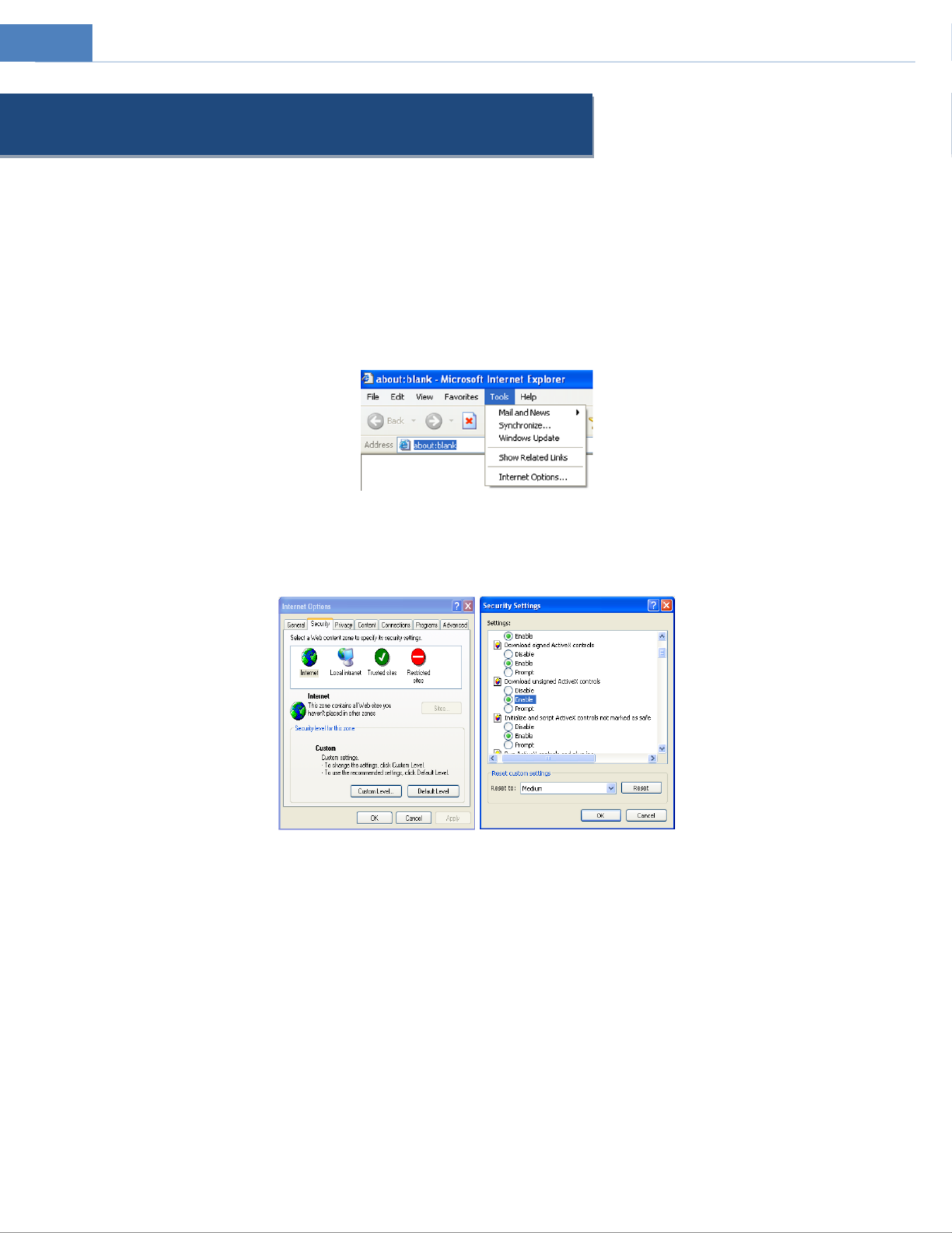
Internet Explorer cannot download ActiveX control.
IE browser may be set up to block ActiveX. Follow the steps below.
1. Open IE browser and then click Tools Internet Options. →
2.Select Security Custom Level. →
3. Enable all the options under “ActiveX controls and plug ins”- .
4. Click to finish setup. OK
No sound can be heard.
1. Audio input device is not connected. Please connect and try again.
2. Audio function is not enabled at the corresponding channel. Please enable this function.

49
Appendix 2 Specifications
Specification /Model
O5B2
Camera
Image Sensor
1/2.7 CMOS "
Image Size
2592 1944×
Electronic Shutter
1/30s~1/100000s
Iris Type
Fixed Iris
Min. llumination
0.02lux@F1.6, AGC ON; 0 lux with IR;
Lens
2.8mm@F1.6, horizontal FoV:98.5°, vertical FoV:82.1°, diagonal FoV:110.9°
Lens Mount
M12
Day&Night
ICR
WDR
120dB
Digital NR
3D DNR
Angle Adjustment
Pan: 0°~360°; Tilt 0°~80°; Rotation:0°~360°
Image
Video
Compression
H.265+/H.265/ H.264+/H.264/MJPEG
H.264 Type
Baseline profile/main profile/high profile
Video Bit Rate
64Kbps~8Mbps
Resolution
5MP (2592×1944), 4MP (2592×1520), 2K(2560×1440), 3MP (2304×1296), (1920×1080)1080P ,
720P(1280×720), D1, CIF, 480×240
Main Stream
60Hz:5MP/4MP/2K/3MP/ P(1~30fps) 50Hz: 4MP/2K/3MP/ P(1~25fps) 1080 720P/ ; 1080 720P/
HFR mode: 60Hz: P(1~60fps); 50Hz: P(1~50fps); 1080 720P/ 1080 720P/
Sub Stream
60Hz: 720P/D1/CIF(1~30fps) 50Hz: 720P/D1/CIF (1~25fps) ;
Third Stream
60Hz: CIF/ D1/480×240 (1~30fps) 50Hz: CIF/D1/ 480×240 (1~25fps) ;
Image Settings
BLC, HLC, Defog, Saturation, Brightness, Hue, Contrast, Wide Dynamic, Sharpness, NR, etc.
adjustable through client or web browser
ROI
Support
Interfaces
Network
RJ45
Auido
1CH audio input
Reset
Yes
Storage
Built-in micro SD card slot; up to 256GB
Fucntion
Remote
Monitoring
Web browser, SecureGuard CMS/VMS, Apple TV, Amazon Fire TV, Speco Blue
Online
Connection
Support simultaneous monitoring for up to 10 users and multi-stream transmission
Network Protocol
UDP, IPv4, IPv6, DHCP, NTP, RTSP, RTP, RTCP, ICMP, IGMP, PPPoE, DDNS, SMTP, FTP, SNMP,HTTP,
802.1x, UPnP, HTTPs, QoS
Interface Protocol
ONVIF
Storage
Network remote storage, micro SD card storage
Smart Alarm
Motion detection, SD card Full, SD card error, abnormal video signal detection, line crossing
detection(human/vehicle classification), intrusion detection(human/vehicle classification),region
entrance, region exiting detection, people/vehicle counting, face detection, face capture
Others
IR Distance
98ft
Protection Grade
IP67
Power
DC12V/PoE
Power Consumption
< 7.5W
Opterating
Environment
Temperature: - °F~ °F; Relative Humidity: less than 95% (non-condensing) 40 140
Dimension (mm)
2.9 ×2.9 ×6.7 (D) ”(W) ”(H) ”
Weight (net)
Approx.0.9lbs
Installation
Wall mounting; ceiling mounting

50
Specification /Model
O5B2M
Camera
Image Sensor
1/2.7 CMOS "
Image Size
2592×1944
Electronic Shutter
1/30s~1/100000s
Iris Type
DC Iris
Min. llumination
0.02 lux@F1.6,AGC ON; 0 lux with IR
Lens
2.8~12mm@F1.4, motorized
7~22mm@F1.6, motorized
Field of View
H: 95.1°~30°; V: 78.7°~22.8°; D: 107.6°~37.1°
H: 41°~16.8°; V: 31.3°~12.7°; D: 50°~21°
Lens Mount
Ø14
Day&Night
ICR
WDR
120dB
Digital NR
3D DNR
Angle Adjustment
Pan: 0°~360°; Tilt 0°~90°; Rotation:0°~360°
Image
Video
Compression
H.265+/H.265/ H.264+/H.264/MJPEG
H.264 Type
Baseline profile/main profile/high profile
Video Bit Rate
64Kbps~8Mbps
Resolution
5MP (2592×1944), 4MP (2592×1520), 2K(2560×1440), 3MP (2304×1296), 1080P (1920×1080),
720P(1280×720), D1, CIF, 480×240
Main Stream
60Hz:5MP/4MP/2K/3MP/1080P/720P(1~30fps); 50Hz: 4MP/2K/3MP/1080P/720P(1~25fps)
HFR mode: 60Hz: 1080P/720P(1~60fps); 50Hz: 1080P/720P(1~50fps);
Sub Stream
60Hz: 720P/D1/CIF(1~30fps); 50Hz: 720P/D1/CIF (1~25fps)
Third Stream
60Hz: CIF/ D1/480×240 (1~30fps); 50Hz: CIF/D1/ 480×240 (1~25fps)
Image Settings
BLC, HLC, Defog, Saturation, Brightness, Chroma, Contrast, Wide Dynamic, Sharpen, NR, etc. adjustable
through client or web browser
ROI
Support
Interfaces
Network
RJ45
Auido
1CH audio input; 1CH audio output
Video
CVBS ouput (BNC×1)
Reset
Yes
Storage
Built-in micro SD card storage slot, up to 256GB
Alarm
1CH Alarm input; 1CH Alarm Ouput
Fucntion
Remote
Monitoring
Web browser, SecureGuard CMS/VMS, Apple TV, Amazon Fire TV, Speco Blue
Online
Connection
Support simultaneous monitoring for up to 10 users and multi-stream transmission
Network Protocol
UDP, IPv4, IPv6, DHCP, NTP, RTSP, RTP, RTCP, ICMP, IGMP, PPPoE, DDNS, SMTP, FTP, SNMP,HTTP, 802.1x,
UPnP, HTTPs, QoS
Interface Protocol
ONVIF
Storage
Network remote storage, micro SD card storage
Smart Alarm
Motion detection, Sensor detection, SD card Full, SD card error, IP address conflict, cable
disconneciton, abnormal video signal detection, line crossing detection(human/vehicle classification),
intrusion detection(human/vehicle classification), people/vehicle counting, region entrance, region
exiting detection, face detection, face capture
Others
IR Distance
229ft
328ft
Protection Grade
IP67
Power
DC12V/PoE
Power Consumption
< 12.5W
Opterating
Environment
Temperature: - °F~ °F; Relative Humidity: less than 95% (non-condensing) 40 140
Dimension (mm)
3.94 ×3.5 × (D) ”(W) ”(H) 11”
Weight (net)
Approx. 2.29lbs
Installation
Wall mounting; ceiling mounting

51
Specification /Model
O5D2
Camera
Image Sensor
1/2.7 CMOS "
Image Size
2592 1944×
Electronic Shutter
1/30s~1/100000s
Iris Type
Fixed Iris
Min. llumination
0.02lux@F1.6, AGC ON; 0 lux with IR
Lens
2.8mm@F1.6, horizontal FoV:98.5°, vertical FoV:82.1°, diagonal FoV:110.9°
Lens Mount
M12
Day&Night
ICR
WDR
120dB
Digital NR
3D DNR
Angle Adjustment
Pan: 0°~355°; Tilt 0°~67°; Rotation:0°~355°
Image
Video Compression
H.265+/H.265/ H.264+/H.264/MJPEG
H.264 Type
Baseline profile/main profile/high profile
Video Bit Rate
64Kbps~8Mbps
Resolution
5MP (2592×1944), 4MP (2592×1520), 2K(2560×1440), 3MP (2304×1296), (1920×1080)1080P ,
720P(1280×720), D1, CIF, 480×240
Main Stream
60Hz:5MP/4MP/2K/3MP/ P(1~30fps) 50Hz: 4MP/2K/3MP/ P(1~25fps) 1080 720P/ ; 1080 720P/
HFR mode: 60Hz: P(1~60fps); 50Hz: P(1~50fps); 1080 720P/ 1080 720P/
Sub Stream
60Hz: 720P/D1/CIF(1~30fps) 50Hz: 720P/D1/CIF (1~25fps) ;
Third Stream
60Hz: CIF/ D1/480×240 (1~30fps) 50Hz: CIF/D1/ 480×240 (1~25fps) ;
Image Settings
BLC, HLC, Defog, Saturation, Brightness, Chroma, Contrast, Wide Dynamic, Sharpen, NR, etc.
adjustable through client or web browser
ROI
Support
Interfaces
Network
RJ45
Auido
1CH audio input; 1CH Built-in MIC
Alarm
1CH alarm input; 1CH alarm output
Reset
Yes
Storage
Built-in micro SD card slot; up to 256GB
Fucntion
Remote Monitoring
Web browser, SecureGuard CMS/VMS, Apple TV, Amazon Fire TV, Speco Blue
Online Connection
Support simultaneous monitoring for up to 10 users and multi-stream transmission
Network Protocol
UDP, IPv4, IPv6, DHCP, NTP, RTSP, RTP, RTCP, ICMP, IGMP, PPPoE, DDNS, SMTP, FTP, SNMP,HTTP,
802.1x, UPnP, HTTPs, QoS
Interface Protocol
ONVIF
Storage
Network remote storage, micro SD card storage
Smart Alarm
Motion detection, Sensor detection, SD card Full, SD card error, IP address conflict, cable
disconneciton, abnormal video signal detection, line crossing detection(human/vehicle
classification), intrusion detection(human/vehicle classification), people/vehicle counting, region
entrance, region exiting detection, face detection, face capture
IR Distance
98ft
Protection Grade
IP67&IK10
Power
DC12V/PoE
Power Consumption
< 6W
Opterating
Environment
Temperature: - °F~ °F; Relative Humidity: less than 95% (non-condensing) 40 140
Dimension (mm)
Ø4.68 ×3.45 ” ”
Weight (net)
Approx. 1.43 lbs
Installation
Ceiling mounting (Wall mounting available with the junction box and bracket)

52
Specification /Model
O5D2M
Camera
Image Sensor
1/2.7 CMOS "
Image Size
2592 1944×
Electronic Shutter
1/30s~1/100000s
Iris Type
DC Iris
Min. llumination
0.01 lux@F1.4,AGC ON; 0 lux with IR
Lens
2.8~12mm@F1.4, horizontal FoV: 95.1°~ 30°; vertical V: 78.7°~22.8°; Fo
Diagonal FoV: 107.6°~37.1°
Lens Mount
Ø14
Day&Night
ICR
WDR
120dB
Digital NR
3D DNR
Angle Adjustment
Pan: 0°~345°; Tilt 0°~77°; Rotation:0°~345°
Image
Video Compression
H.265+/H.265/ H.264+/H.264/MJPEG
H.264 Type
Baseline profile/main profile/high profile
Video Bit Rate
64Kbps~8Mbps
Resolution
5MP (2592×1944), 4MP (2592×1520), 2K(2560×1440), 3MP (2304×1296), (1920×1080)1080P ,
720P(1280×720), D1, CIF, 480×240
Main Stream
60Hz:5MP/4MP/2K/3MP/ P(1~30fps) 50Hz: 4MP/2K/3MP/ P(1~25fps) 1080 720P/ ; 1080 720P/
HFR mode: 60Hz: P(1~60fps); 50Hz: P(1~50fps); 1080 720P/ 1080 720P/
Sub Stream
60Hz: 720P/D1/CIF(1~30fps) 50Hz: 720P/D1/CIF (1~25fps) ;
Third Stream
60Hz: CIF/ D1/480×240 (1~30fps) 50Hz: CIF/D1/ 480×240 (1~25fps) ;
Image Settings
BLC, HLC, Defog, Saturation, Brightness, Chroma, Contrast, Wide Dynamic, Sharpen, NR, etc.
adjustable through client or web browser
ROI
Support
Interfaces
Network
RJ45
Auido
1CH audio input; 1CH audio output; 1CH built-in MIC
Video
CVBS ouput (BNC ) ×1
Reset
Yes
Storage
Built-in micro SD card storage slot, up to 256GB
Alarm
1CH Alarm input; 1CH Alarm Ouput
Fucntion
Remote Monitoring
Web browser, SecureGuard CMS/VMS, Apple TV, Amazon Fire TV, Speco Blue
Online Connection
Support simultaneous monitoring for up to 10 users and multi-stream transmission
Network Protocol
UDP, IPv4, IPv6, DHCP, NTP, RTSP, RTP, RTCP, ICMP, IGMP, PPPoE, DDNS, SMTP, FTP, SNMP,HTTP,
802.1x, UPnP, HTTPs, QoS
Interface Protocol
ONVIF
Storage
Network remote storage, micro SD card storage
Smart Alarm
Motion detection, Sensor detection, SD card Full, SD card error, IP address conflict, cable
disconneciton, abnormal video signal detection, line crossing detection(human/vehicle
classification), intrusion detection(human/vehicle classification), people/vehicle counting, region
entrance, region exiting detection, face detection, face capture
IR Distance
164ft
Protection Grade
IP67&IK10
Power
DC12V/PoE
Power Consumption
< 9W
Opterating
Environment
Temperature: - °F~ °F; Relative Humidity: less than 95% (non-condensing) 40 140
Dimension (mm)
Ø5.55 ×3.94 ” ”
Weight (net)
Approx. 2.05 lbs
Installation
Ceiling mounting (Wall mounting available with the junction box and bracket)

54
Specification /Model
O5T2M
Camera
Image Sensor
1/2.7 CMOS "
Image Size
2592 1944×
Electronic Shutter
1/30s~1/100000s
Iris Type
DC Iris
Min. llumination
0.01 lux@F1.4,AGC ON; 0 lux with IR
Lens
2.8~12mm@F1.4, horizontal FoV: 95.1°~ 30°; vertical V: 78.7°~22.8°; Fo
Diagonal FoV: 107.6°~37.1°
Lens Mount
Ø14
Day&Night
ICR
WDR
120dB
Digital NR
3D DNR
Angle Adjustment
Pan: 0°~360°; Tilt 0°~80° Rotation:0°~360° ;
Image
Video Compression
H.265+/H.265/ H.264+/H.264/MJPEG
H.264 Type
Baseline profile/main profile/high profile
Video Bit Rate
64Kbps~8Mbps
Resolution
5MP (2592×1944), 4MP (2592×1520), 2K(2560×1440), 3MP (2304×1296), (1920×1080)1080P ,
720P(1280×720), D1, CIF, 480×240
Main Stream
60Hz:5MP/4MP/2K/3MP/ P(1~30fps) 50Hz: 4MP/2K/3MP/ P(1~25fps) 1080 720P/ ; 1080 720P/
HFR mode: 60Hz: P(1~60fps); 50Hz: P(1~50fps); 1080 720P/ 1080 720P/
Sub Stream
60Hz: 720P/D1/CIF(1~30fps) 50Hz: 720P/D1/CIF (1~25fps) ;
Third Stream
60Hz: CIF/ D1/480×240 (1~30fps) 50Hz: CIF/D1/ 480×240 (1~25fps) ;
Image Settings
BLC, HLC, Defog, Saturation, Brightness, Chroma, Contrast, Wide Dynamic, Sharpen, NR, etc. adjustable
through client or web browser
ROI
Support
Interfaces
Network
RJ45
Auido
1CH audio input; Built-in MIC ×1
Reset
Yes
Storage
Built-in micro SD card slot; up to 256GB
Fucntion
Remote Monitoring
Web browser, SecureGuard CMS/VMS, Apple TV, Amazon Fire TV, Speco Blue
Online Connection
Support simultaneous monitoring for up to 10 users and multi-stream transmission
Network Protocol
UDP, IPv4, IPv6, DHCP, NTP, RTSP, RTP, RTCP, ICMP, IGMP, PPPoE, DDNS, SMTP, FTP, SNMP,HTTP, 802.1x,
UPnP, HTTPs, QoS
Interface Protocol
ONVIF
Storage
Network remote storage, micro SD card storage
Smart Alarm
Motion detection, SD card Full, SD card error, abnormal video signal detection, line crossing
detection(human/vehicle classification), intrusion detection(human/vehicle classification),
people/vehicle counting, face detection, face capture
Protection Grade
IP67
Power
DC12V/PoE
Power Consumption
< 9W
IR Distance
164ft
Opterating
Environment
Temperature: - °F~ °F; Relative Humidity: less than 95% (non-condensing) 40 140
Dimension (mm)
4.39 (Ø) ×3.92 ” ”
Weight (net)
Approx. 1.45lbs
Installation
Ceiling mounting (Wall mounting available with the junction box and bracket)

55
Specification /Model
O5P2
Camera
Image Sensor
1/2.7 CMOS "
Image Size
2592 1944×
Electronic Shutter
1/30s~1/100000s
Iris Type
Fixed Iris
Min. llumination
0.02lux@F1.6, AGC ON; 0 lux with IR
Lens
2.8mm@F1.6, horizontal FoV:98.5°, vertical FoV:82.1°, diagonal FoV:110.9°
Lens Mount
M12
Day&Night
ICR
WDR
120dB
Digital NR
3D DNR
Angle Adjustment
Pan: 0°~360°; Tilt 0°~75°; Rotation:0°~350°
Image
Video Compression
H.265+/H.265/ H.264+/H.264/MJPEG
H.264 Type
Baseline profile/main profile/high profile
Video Bit Rate
64Kbps~8Mbps
Resolution
5MP (2592×1944), 4MP (2592×1520), 2K(2560×1440), 3MP (2304×1296), (1920×1080)1080P ,
720P(1280×720), D1, CIF, 480×240
Main Stream
60Hz:5MP/4MP/2K/3MP/ P(1~30fps) 50Hz: 4MP/2K/3MP/ P(1~25fps) 1080 720P/ ; 1080 720P/
HFR mode: 60Hz: P(1~60fps); 50Hz: P(1~50fps); 1080 720P/ 1080 720P/
Sub Stream
60Hz: 720P/D1/CIF(1~30fps) 50Hz: 720P/D1/CIF (1~25fps) ;
Third Stream
60Hz: CIF/ D1/480×240 (1~30fps) 50Hz: CIF/D1/ 480×240 (1~25fps) ;
Image Settings
BLC, HLC, Defog, Saturation, Brightness, Chroma, Contrast, Wide Dynamic, Sharpen, NR, etc. adjustable
through client or web browser
ROI
Support
Interfaces
Network
RJ45
Auido
1CH audio input; Built-in MIC ×1
Reset
Yes
Storage
Built-in micro SD card slot; up to 256GB
Fucntion
Remote Monitoring
Web browser, SecureGuard CMS/VMS, Apple TV, Amazon Fire TV, Speco Blue
Online Connection
Support simultaneous monitoring for up to 10 users and multi-stream transmission
Network Protocol
UDP, IPv4, IPv6, DHCP, NTP, RTSP, RTP, RTCP, ICMP, IGMP, PPPoE, DDNS, SMTP, FTP, SNMP,HTTP, 802.1x,
UPnP, HTTPs, QoS
Interface Protocol
ONVIF
Storage
Network remote storage, micro SD card storage
Smart Alarm
Motion detection, SD card Full, SD card error, abnormal video signal detection, line crossing
detection(human/vehicle classification), intrusion detection(human/vehicle classification),
people/vehicle counting, face detection, face capture
Protection Grade
IP66
Power
DC12V/PoE
Power Consumption
< 6W
IR Distance
66ft
Opterating
Environment
Temperature: - °F~ °F; Relative Humidity: less than 95% (non-condensing) 40 140
Dimension (mm)
4.33 (Ø) × 2.28 ” ”
Weight (net)
Approx. lbs 0.83
Installation
Ceiling mounting (Wall mounting available with the junction box and bracket)

56
Models: O / O5B2M/ O5D2/ O5D2M/ O5T2/ O5T2M/ O5P2 5B2
Federal Communications Commission (FCC) Statements
This device complies with Part 15 of the FCC Rules. Operation is subject to the following two conditions: (1) This device may not cause harmful interference,
and (2) This device must accept any interference received, including interference that may cause undesired operation.
FCC Responsible Party:
Speco Technologies
200 New Highway
Amityville, NY11701
www.specotech.com
Produkt Specifikationer
| Mærke: | Speco Technologies |
| Kategori: | sikkerhedskamera |
| Model: | O5T2M |
Har du brug for hjælp?
Hvis du har brug for hjælp til Speco Technologies O5T2M stil et spørgsmål nedenfor, og andre brugere vil svare dig
sikkerhedskamera Speco Technologies Manualer

16 August 2024
14 August 2024
13 August 2024
12 August 2024
10 August 2024
8 August 2024
7 August 2024
6 August 2024
sikkerhedskamera Manualer
- sikkerhedskamera Canon
- sikkerhedskamera Fenton
- sikkerhedskamera TP-Link
- sikkerhedskamera Philips
- sikkerhedskamera Motorola
- sikkerhedskamera Nedis
- sikkerhedskamera Abus
- sikkerhedskamera Hama
- sikkerhedskamera Smartwares
- sikkerhedskamera Trust
- sikkerhedskamera Topcom
- sikkerhedskamera JVC
- sikkerhedskamera Honeywell
- sikkerhedskamera König
- sikkerhedskamera Elro
- sikkerhedskamera Gembird
- sikkerhedskamera Netgear
- sikkerhedskamera Maginon
- sikkerhedskamera Yale
- sikkerhedskamera Alecto
- sikkerhedskamera Niceboy
- sikkerhedskamera APC
- sikkerhedskamera Foscam
- sikkerhedskamera Lorex
- sikkerhedskamera Vivotek
- sikkerhedskamera Eufy
- sikkerhedskamera Swan
- sikkerhedskamera Overmax
- sikkerhedskamera Somfy
- sikkerhedskamera Hikvision
- sikkerhedskamera Eminent
- sikkerhedskamera Axis
- sikkerhedskamera ACTi
- sikkerhedskamera Nordväl
- sikkerhedskamera ZKTeco
- sikkerhedskamera First Alert
- sikkerhedskamera Promise Technology
- sikkerhedskamera V-TAC
- sikkerhedskamera IDIS
- sikkerhedskamera AVer
- sikkerhedskamera Ferguson
- sikkerhedskamera Profile
- sikkerhedskamera Apeman
- sikkerhedskamera ATN
- sikkerhedskamera Ubiquiti
- sikkerhedskamera Dahua
- sikkerhedskamera Targa
- sikkerhedskamera Miniland
- sikkerhedskamera Humax
- sikkerhedskamera Gira
- sikkerhedskamera Iget
- sikkerhedskamera Iluv
- sikkerhedskamera Storage Options
- sikkerhedskamera Swisstone
- sikkerhedskamera Sinji
- sikkerhedskamera SAB
- sikkerhedskamera Moen
- sikkerhedskamera Pelco
- sikkerhedskamera Sricam
- sikkerhedskamera Kompernass
- sikkerhedskamera Brinno
- sikkerhedskamera Tenvis
- sikkerhedskamera Jablocom
- sikkerhedskamera Beseye
- sikkerhedskamera Exacq
- sikkerhedskamera Brickcom
- sikkerhedskamera Home Protector
- sikkerhedskamera Escam
- sikkerhedskamera Mr Safe
- sikkerhedskamera Duramaxx
- sikkerhedskamera EasyN
- sikkerhedskamera Arecont Vision
Nyeste sikkerhedskamera Manualer
24 Februar 2025
24 Februar 2025
23 Februar 2025
21 Februar 2025
19 Februar 2025
13 Februar 2025
13 Februar 2025
13 Februar 2025
11 Februar 2025
11 Februar 2025