Technoline TM 3010 Manual
Technoline
Termostat
TM 3010
Læs nedenfor 📖 manual på dansk for Technoline TM 3010 (4 sider) i kategorien Termostat. Denne guide var nyttig for 32 personer og blev bedømt med 4.5 stjerner i gennemsnit af 2 brugere
Side 1/4
A
B
C
D
E
F
G
H
I
TM 3010
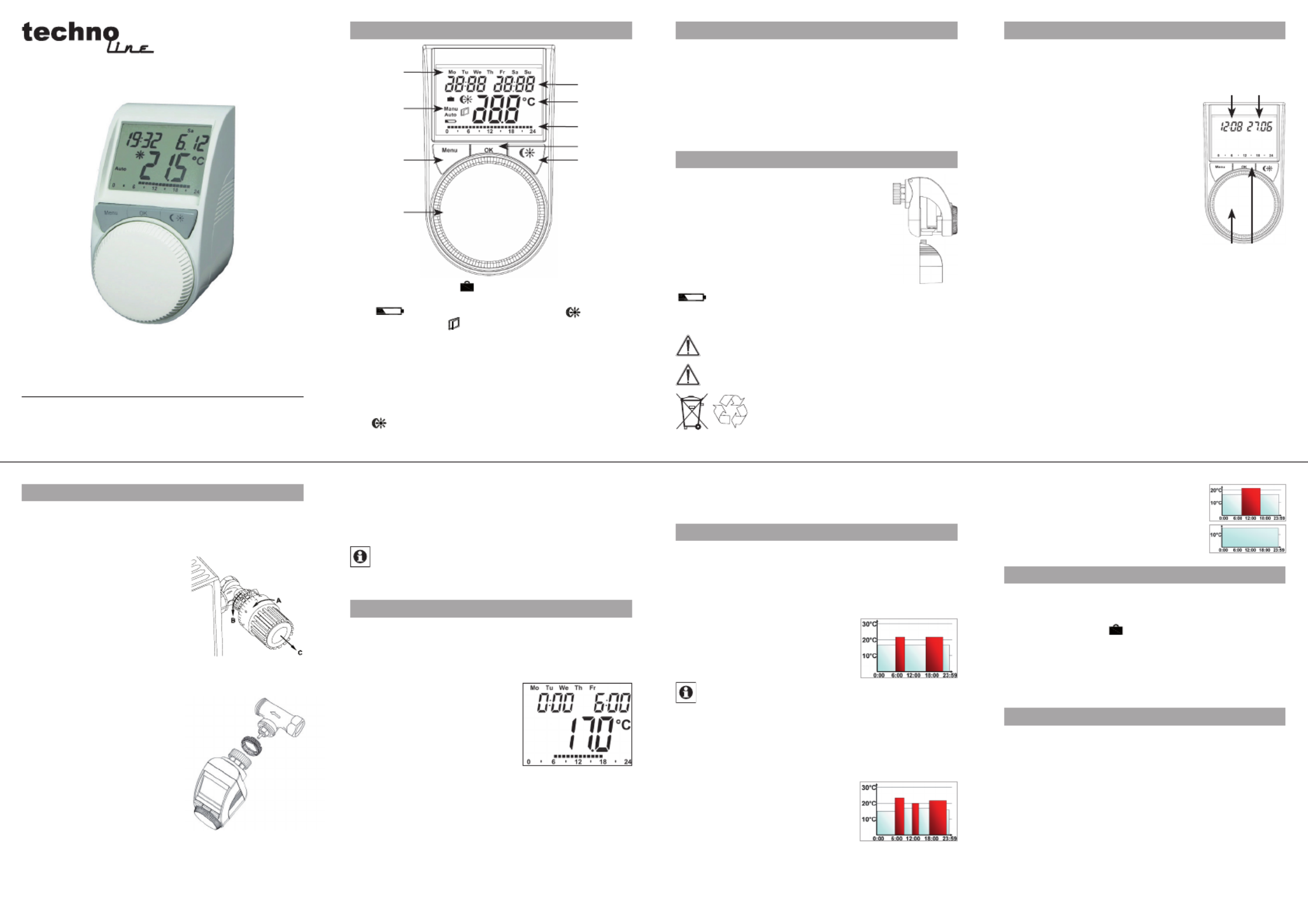
Operation and display General function
This energy-saving controller for radiators can be used
to control room temperature on the basis of time. The
actuator moves a valve, thereby allowing the amount of
heat flowing to the heating appliance to be controlled. The
controller is compatible with all standard heating appli-
ance valves. The large illuminated display ensures user-
friendly operation.
Installation can be achieved in 3 easy steps.
Step 1: Inserting (replacing) the batteries
Remove the battery compartment cover.•
Insert 2 new Mignon batteries (LR6/AA) •
into the side battery compartments, en-
suring they are the right way round.
Reattach the battery compartment cover •
and click into place.
New alkaline batteries have a life of ap-
proximately three years. A battery symbol
( ) will indicate when the batteries need to be replaced.
After removing the old batteries, please wait approximately
1 minute before inserting the new ones.
Never recharge standard batteries.
Doing so will present a risk of explosion.
Do not throw the batteries into a fire.
Do not short-circuit batteries.
Used batteries should not be disposed
of with regular domestic waste. Instead,
they should be taken to your local battery
disposal point.
Step 2: Setting the date and time of day
The firmware version number will be displayed briefly once
you have inserted/replaced the batteries and then you will be
automatically prompted to set the date and time of day.
Use the setting wheel (C) to set •
the year (B).
Confirm with OK (D).•
Use the setting wheel (C) to set •
the month (B).
Confirm with OK (D).•
Use the setting wheel (C) to set •
the day (B).
Confirm with OK (D).•
Use the setting wheel (C) to set •
the hour (A).
Confirm with OK (D).•
Use the setting wheel (C) to set the minute (A).•
Confirm with OK (D).•
The motor will start moving back the control pin while the
entries are still being made.
If “InS” is displayed with a rotating “•
∏
” symbol, this
indicates that the motor is still moving back. Once the
device is ready for the actuator to be installed on the
valve, just “InS” will appear on the display.
The weekly program and other settings can be cus-•
tomised prior to installation. To do this, press the menu
button when “InS” is shown on the display. For further
details, please see “4. Configuration menu”.
O nce p rog ram m ing i s com p le t e , “In S ” will re appe ar o n t he •
display and installation (Step 3) can commence.
Step 3: Installing the energy-saving controller
The actuator can be installed on all standard heating
valves. There is no need to drain away water or fiddle
around with the heating system before doing this. First,
you need to remove the old thermostat dial:
Turn the thermostat dial anti- •
clockwise as far as it will go (A).
Release the thermal ring of the •
thermostat (B).
Remove the thermostat from •
the valve (C).
An adapter will need to be used in
the case of certain valves. Adapt-
ers for Danfoss valves (RA, RAV,
RAVL) are included in the scope of delivery. For details,
please refer to the adapter overview (see 18).
The adapter must be placed on the valve •
and turned until it is secure-
ly seated.
In the case of the RAV adapter, •
the extension supplied must be
attached to the valve tappet.
The RA and RAV adapters must, •
in addition, be secured by means
of the bolt and nut supplied.
The energy-saving controller can
only be installed if “InS” is show-
ing on the display. Following installation, the actuator will
perform an adjustment run so that it can adapt to the valve.
During this process, “AdA” will be displayed.
Place the actuator on the valve.•
Tighten the union nut.•
“InS” will appear on the display, press the OK button.•
The actuator will perform an adjustment run (“AdA” will •
appear on the display, operation not possible).
After that, the actuator will be ready for operation (Auto •
mode).
If the adjustment run was initiated prior to installa-
tion, or if an error message will be displayed (F1, F2,
F3); press OK to move the motor back to the “InS”
position.
1. Setting the weekly program
The weekly program allows you to set up to 3 separate
heating periods (7 switching times) for each day of the
week. Programming is performed in relation to the se-
lected days, for which temperatures must be stored for a
period from 00:00 to 23:59.
Press and hold down the menu •
button for more than 3 seconds.
“Pro” will appear on the display.•
Confirm with OK.•
“dAy” will appear on the display. •
The setting wheel can be used
to select an individual day of the
week, all working days, the weekend or the entire week
(example shows working days selected).
Confirm with OK.•
Use the setting wheel to set the first time segment (exam-•
ple shows 0:00 to 6:00).
Confirm with OK.•
Then, select the required temperature for the selected time •
segment (example shows 17.0°C).
Confirm with OK.•
Keep repeating this process until you have finished storing •
temperatures for the period from 0:00 to 23:59.
In Auto mode, the temperature can be modified at any time
via the setting wheel. The modified temperature will then
be retained until the next program changeover.
2. Weekly program: Examples
The energy-saving controller allows you to store up to 3
heating periods (7 switching times) with individual temper-
ature settings for each day of the week. The factory set-
ting consists of two heating phases (from 6:00 until 9:00
and from 17:00 until 23:00 respectively) for every single
day of the week:
From 00:00 to 06:00 17.0°C
From 06:00 to 09:00 21.0°C
From 09:00 to 17:00 17.0°C
From 17:00 to 23:00 21.0°C
From 23:00 to 23:59 17.0°C
To represent the switching periods, the display shows
bars for every other switching interval. In this exam-
ple, no bars are shown for the interval from 0:00 to
6:00. Bars are only shown on the display for the in-
tervals from 6:00 to 9:00 and from 17:00 to 23:00.
If a room also needs to be heated at around noon, the cor-
responding program might look like this:
Monday to Sunday
From 00:00 to 06:00 16.0°C
From 06:00 to 09:00 22.0°C
From 09:00 to 12:00 17.0°C
From 12:00 to 14:00 20.0°C
From 14:00 to 17:30 17.0°C
From 17:30 to 23:30 21.0°C
From 23:30 to 23:59 16.0°C
If you have a home office and only want it to be heated
during the day on working days, you can program the fol-
lowing times:
Monday to Friday
From 00:00 to 08:30 17.0°C
From 08:30 to 17:00 21.0°C
From 17:00 to 23:59 17.0°C
Saturday and Sunday
From 00:00 to 23:59 15.0°C
3. Operating modes
To switch between the 3 operating modes described below,
press the menu button briefly (these operating modes can
only be selected following installation/Step 3):
Holiday function• ( Set a temperature that is to be ):
maintained until a fixed point in time.
Manu: • Manual operation – The temperature is set manu-
ally using the setting wheel.
Auto: • W e ek ly p ro gra m – Th e temp er atur e is con trol led aut o-
matically in accordance with the stored weekly program.
4. Configuration menu
The configuration menu can be used to modify settings.
To access this menu, press and hold down the menu
button (for more than 3 seconds).
Pro: For setting the weekly program (see Section “1 Set-•
ting the weekly program”)
dAt: For modifying the time of day and date•
POS: For querying the actuator’s current position•
dSt: Automatic switchover at the start or end of daylight •
saving time can be deactivated.
AEr: For setting the “window open” temperature and •
time so that the temperature is automatically reduced
in the event of ventilation
tOF: For setting the offset temperature•
rES: For restoring the factory settings•
Please read this manual carefully in order to help you put
the device into operation. Keep the manual handy so you
can refer to it at a later date!
A Day of the week
B Holiday function ( ), manual operation (Manu), au-
tomatic operation (Auto), “battery empty” symbol
( ), set-back/comfort temperature ( ), “window
open” symbol ( )
C Menu button: Press and hold down the button for more
than 3 seconds to open the configuration menu
D Setting wheel: For making adjustments (e.g. temperature)
E Time and date indicator, menu items, functions
F Current temperature setting
G Switching periods set within weekly program
H OK button: For confirming/saving
I button: For switching between set-back and com-
fort temperatures
5
2
6
3
7
4
8
A
C
B
D
Produkt Specifikationer
| Mærke: | Technoline |
| Kategori: | Termostat |
| Model: | TM 3010 |
Har du brug for hjælp?
Hvis du har brug for hjælp til Technoline TM 3010 stil et spørgsmål nedenfor, og andre brugere vil svare dig
Termostat Technoline Manualer

30 Juli 2024
Termostat Manualer
- Termostat Bosch
- Termostat SilverCrest
- Termostat Siemens
- Termostat GE
- Termostat Daikin
- Termostat Panasonic
- Termostat Hager
- Termostat TP-Link
- Termostat AEG
- Termostat Gigaset
- Termostat Finder
- Termostat Atag
- Termostat Emos
- Termostat Google
- Termostat Worcester
- Termostat TFA
- Termostat Baxi
- Termostat Carel
- Termostat De Dietrich
- Termostat Buderus
- Termostat AVM
- Termostat Hama
- Termostat Theben
- Termostat Busch-Jaeger
- Termostat Trotec
- Termostat Honeywell
- Termostat Ariston Thermo
- Termostat Truma
- Termostat Elro
- Termostat Max
- Termostat Vaillant
- Termostat RADEMACHER
- Termostat Carrier
- Termostat Danfoss
- Termostat Wolf
- Termostat Nest
- Termostat Dimplex
- Termostat Eberle
- Termostat Grässlin
- Termostat Heimeier
- Termostat Junkers
- Termostat Salus
- Termostat TrickleStar
- Termostat Weishaupt
- Termostat Alecto
- Termostat Westfalia
- Termostat Boneco
- Termostat HQ
- Termostat EnerGenie
- Termostat Schneider
- Termostat Basetech
- Termostat Tesla
- Termostat Grohe
- Termostat Ferroli
- Termostat Velleman
- Termostat Perel
- Termostat Joblotron
- Termostat Saunier Duval
- Termostat JUNG
- Termostat Vemer
- Termostat ORNO
- Termostat Watts
- Termostat Ambiano
- Termostat Netatmo
- Termostat Somfy
- Termostat EQ3
- Termostat Techno Line
- Termostat Brennenstuhl
- Termostat Cotech
- Termostat Intergas
- Termostat Devolo
- Termostat Aube
- Termostat Elgato
- Termostat Renkforce
- Termostat SPC
- Termostat Hunter
- Termostat Viessmann
- Termostat Nobo
- Termostat Orbis
- Termostat Remeha
- Termostat Seitron
- Termostat Stiebel Eltron
- Termostat ACV
- Termostat Mikoterm
- Termostat Hive
- Termostat Tado
- Termostat Fibaro
- Termostat Noma
- Termostat POER
- Termostat EQ-3
- Termostat Vimar
- Termostat Oregon Scientific
- Termostat Corbero
- Termostat Remko
- Termostat Nexa
- Termostat Avidsen
- Termostat Crestron
- Termostat Emerson
- Termostat Elektrobock
- Termostat Delta Dore
- Termostat Homematic IP
- Termostat H-Tronic
- Termostat Schwaiger
- Termostat Emko
- Termostat Bearware
- Termostat Ferguson
- Termostat Nefit
- Termostat Amfra
- Termostat Itho
- Termostat Fenix
- Termostat Magnum
- Termostat Horstmann
- Termostat Oventrop
- Termostat King
- Termostat Arnold Rak
- Termostat Heatmiser
- Termostat Itho-Daalderop
- Termostat Bticino
- Termostat Sygonix
- Termostat Plieger
- Termostat Conrad
- Termostat Zehnder
- Termostat Bulex
- Termostat UPM
- Termostat Optima
- Termostat AWB
- Termostat Xavax
- Termostat Fantini Cosmi
- Termostat Niko
- Termostat Gira
- Termostat Eneco
- Termostat Frico
- Termostat Vasco
- Termostat Radson
- Termostat Go Green
- Termostat Extraflame
- Termostat ICY
- Termostat HomeMatic
- Termostat Computherm
- Termostat Brink
- Termostat Drayton
- Termostat Heatit
- Termostat 2Heat
- Termostat Bryant
- Termostat Eqiva
- Termostat Etherma
- Termostat Veria
- Termostat Emmeti
- Termostat Thermy
- Termostat Coati
- Termostat Essent
- Termostat ThermoSmart
- Termostat Plugwise
- Termostat Eurotronic
- Termostat Hornbach
- Termostat Tru Components
- Termostat HomePilot
- Termostat Muller
- Termostat Worcester-Bosch
- Termostat Econo-Heat
- Termostat VDH
- Termostat PECO
- Termostat IR-V
- Termostat EasyTemp
- Termostat Intertechno
- Termostat Helios (Amfra)
- Termostat Easy Timer
- Termostat Z-Wave
- Termostat Hugo Muller
- Termostat IMIT
- Termostat Innogy
- Termostat Wallair
- Termostat Maico
- Termostat Levica
- Termostat Ouellet
- Termostat THERMAFLEX
- Termostat Wachendorff
- Termostat STI
- Termostat Yokis
- Termostat ChiliTec
- Termostat Eliwell
- Termostat Johnson Control
- Termostat Webasto
- Termostat Drayton Erie
- Termostat OJ ELECTRONICS
- Termostat Tellur
- Termostat RWE
- Termostat ATTACK
- Termostat Lowes
- Termostat Jumo
- Termostat Warmup
- Termostat Qubino
- Termostat ELKO
- Termostat Gewiss
- Termostat Sinustec
- Termostat Rose LM
- Termostat Otio
- Termostat MundoControl
- Termostat Enda
- Termostat GENERAL Life
- Termostat Oreg
- Termostat Braeburn
Nyeste Termostat Manualer
26 Marts 2025
26 Februar 2025
26 Februar 2025
5 Februar 2025
1 Februar 2025

1 Februar 2025
1 Februar 2025
29 Januar 2025

15 Januar 2025

15 Januar 2025