Adder Link INFINITY 1104T Manual
Læs nedenfor 📖 manual på dansk for Adder Link INFINITY 1104T (172 sider) i kategorien bryter. Denne guide var nyttig for 17 personer og blev bedømt med 4.5 stjerner i gennemsnit af 2 brugere
Side 1/172

ADDERLink® INFINITY 1000 & 2000 Series
ALIF1102, 1104T, 2102, 2122 and 2124T User Guide


INSTALLATION
1
CONFIGURATIONOPERATION
FURTHER
INFORMATION
INDEX
Introduction
Welcome 2 ................................................................................................................
Local feed through 3 ...............................................................................................
Technical Specications .......................................................................................4
ALIF1102 & 1104 unit features .........................................................................5
ALIF2102 unit features ........................................................................................6
ALIF2122 unit features ........................................................................................7
ALIF2124 unit features ........................................................................................8
Supplied items .......................................................................................................9
Supplied items .....................................................................................................10
Optional extras ...................................................................................................11
Installation
Connections ........................................................................................................12
Mounting 12 ..............................................................................................................
TX video links ...............................................................................................13
TX audio links ...............................................................................................13
TX USB links .................................................................................................14
TX power in 15 ..................................................................................................
TX/RX high speed links ..............................................................................16
RX video displays .........................................................................................18
RX audio devices ..........................................................................................19
RX USB devices ............................................................................................20
RX power in 21 ..................................................................................................
Conguration
ALIF conguration via web pages ...................................................................22
Performing a manual factory reset .................................................................23
Placing the device into recovery mode .........................................................24
Conguring dual touchscreens ........................................................................25
Creating an unmanaged matrix 26 .......................................................................
Creating and editing presets ............................................................................27
Operation
Indicators .............................................................................................................28
Using the On Screen Display ...........................................................................29
Port status popups .............................................................................................30
Further information
Getting assistance ..............................................................................................31
Appendix A - Conguration pages .................................................................32
Appendix B - Support for analog and digital audio.....................................52
Appendix C - Tips for success when networking ALIF units ....................53
Appendix D - Troubleshooting ........................................................................55
Appendix E - Glossary ......................................................................................57
Appendix F - Fiber/copper modules and cables ..........................................60
Appendix G - Using the optional ALIF1100/2100 rack shelves ...............61
Appendix H - Open source licenses ..............................................................63
Index
Contents


INSTALLATION
2
CONFIGURATIONOPERATION
FURTHER
INFORMATION
INDEX
Introduction
WELCOME
Thank you for choosing the ADDERLink® INFINITY 1100 and INFINITY 2100 (aka
ALIF1100 and ALIF2100) high performance extenders. The range offers dual-head video,
audio and USB delivered over ber and/or CATx connections. Pixel-perfect color,
accurate picture quality at up to 2560x1600@60Hz and USB2.0 with fast switching.
Product in brief
• Support for dual link speeds up to 1GbE using either CATx and/or ber. Several model
variants available:
• ALIF1102 models have a xed 1GbE CATx port plus an SFP socket for additional
CATx or ber. They also have a single DisplayPort™ video connector,
• ALIF1104 transmitters have a xed 1GbE CATx port plus an SFP socket for
additional CATx or ber. They also have a single HDMI® video connectors,
• ALIF2102 models have a xed 1GbE CATx port plus an SFP socket for additional
CATx or ber. They also have two DisplayPort™ video connectors,
• ALIF2122 models have two SFP sockets for CATx or ber. They also have two
DisplayPort™ video connectors,
• ALIF2124 transmitters have two SFP sockets for CATx or ber. They also have two
HDMI® video connectors.
• Transmitter and receivers from the ALIF2102, ALIF2122 and ALIF2024 variants can be
freely mixed as necessary with the use of appropriate SFP modules,
• Support for 1x 2560x1600@60Hz or 2x 1920x1200@60Hz (ALIF2100 models only),
• Digital stereo audio via the video connections,
• Uni-directional analog audio (with combined headset jack on the receiver),
• Adder’s USB True Emulation for fast switching,
• Support for advance diagnostic and troubleshooting tools,
• Backwards compatibility with existing ALIF range,
• Plug and play.
IMPORTANT: When using AIM to congure ALIF
units, it is vital that all units that you wish to
locate and control are set to their factory default
settings. Otherwise they will not be located by
the AIM server. If necessary, perform a manual
factory reset on each ALIF unit.
Note: If you are using one or more transmitters
within an installation managed by an AIM
server, the AIM server must be running
rmware version or above.5.3
Linking
ALIF1100 and ALIF2100 units can be linked in two mains ways: Direct or Networked.
Direct linking
Where transmitters and receivers are directly linked to each other, very little
conguration action is required, provided that they both have their factory default
settings in place - just link them together. If the standard settings have been changed in a
previous installation, you merely need to perform a manual factory reset on each unit.
Networked linking
Where units are connected via networked links, you can either congure them
individually, or congure them collectively using an AIM server:
• Conguring networked ALIF units individually - In the absence of an AIM server,
unallocated units have the ability to locate each other. You can alter settings via the OSD
on the console connected to the RX unit by pressing CTRL + ALT + C.
• Conguring networked ALIF units collectively - The ADDERLink® INFINITY
Management (AIM) server allows you to congure, control and coordinate any number
of ALIF transmitters and receivers from a single application.
Safety
Please refer to the safety booklet provided in the box before use of this product.
See Start of Life: AIM or Point to Point conguration


INSTALLATION
3
CONFIGURATIONOPERATION
FURTHER
INFORMATION
INDEX
In operation, the user of the console at the ALIF
receiver can use the following hotkey combination
to toggle between the network and local links:
To change from a network link to the local link:
enter CTRL+ALT+L
To change from the local link to a network link:
enter CTRL+ALT +C
to display the OSD and choose
the required connection.
Note: The L and C default hotkeys can be changed
within the AIM control panel.
ALIF2122 RX
LOCAL FEED THROUGH
ALIF receiver units can be congured to support a local link to a separate host PC, via a
dedicated ALIF transmitter, in addition to the main link to the network. The locally linked
PC remains completely isolated from the main network.
To congure this arrangement, ensure that the receiver is using its default IP address and
is directly connected to the transmitter. The transmitter must use its primary network
port, which is the interface using 169.254.1.33 as its default address, and be congured to
either “Auto” or “Allow” for insecure connections (see “Insecure connections” on page
44). The easiest way to do this is to use a factory new or factory reset transmitter, you
can then change any additional settings after connecting it to the receiver.
Notes: For the local feed through feature to operate, the AIM server must be at version 4.8
or greater while the endpoints must be at version 4.0 or greater. The TX must use its primary
network port and be in it’s default conguration, which can be achieved via a new unit or a
factory refresh, when connected to the RX.
Note: ALIF1102 RX units
support a single display.


INSTALLATION
5
CONFIGURATIONOPERATION
FURTHER
INFORMATION
INDEX
ALIF1102 & 1104 UNIT FEATURES
The transmitter and receiver modules are housed within durable, vented enclosures with connectors situated on the front and rear panels. The ALIF1100 units are
characterized by their mix of CATx and SFP ports, plus a single video connector on each variant (DisplayPort™ on the RX and either DisplayPort™ or HDMI® on the TX).
Transmitter - front (both ALIF1102 & ALIF1104) Receiver - front
Receiver - rear
CATx and
SFP link ports
DisplayPort™
video out
USB
ports
Power
in
Analog
audio line
out
Status
indicator
Transmitter - rear (ALIF1102)
USB Power
in
DisplayPort™
video in
Analog
audio in
Status
indicator
Combined
analog audio
headphone/
mic/headset
port
Reset
switch
and status
indicator
USB
ports
CATx and
SFP link
ports
USB AUX port
(for use with
USB-to-serial
converters)
Reset
switch
and status
indicator
Transmitter - rear (ALIF1104)
USB Power
in
HDMI®
video in
Analog
audio in
Status
indicator


INSTALLATION
6
CONFIGURATIONOPERATION
FURTHER
INFORMATION
INDEX
ALIF2102 UNIT FEATURES
The transmitter and receiver modules are housed within durable, vented enclosures with connectors situated on the front and rear panels.
The ALIF2102 units are characterized by their mix of CATx and SFP ports, plus two DisplayPort™ connections.
Transmitter - rear Receiver - rear
Transmitter - front Receiver - front
CATx and
SFP link ports
Primary
display
USB
ports
Power
in
Secondary
display
Analog
audio line
out
Status
indicator
USB Power
in
Primary
video in
Secondary
video in
Analog
audio in
Status
indicator
Combined
analog audio
headphone/
mic/headset
port
Reset
switch
and status
indicator
USB
ports
CATx and
SFP link
ports
USB AUX port
(for use with
USB-to-serial
converters)
Reset
switch
and status
indicator


INSTALLATION
7
CONFIGURATIONOPERATION
FURTHER
INFORMATION
INDEX
2x SFP
link ports
ALIF2122 UNIT FEATURES
The transmitter and receiver modules are housed within durable, vented enclosures with connectors situated on the front and rear panels.
The ALIF2122 units are characterized by their dual SFP ports, plus two DisplayPort™ connections.
Transmitter - rear Receiver - rear
Receiver - front
Primary
display
USB
ports
Power
in
Secondary
display
Analog
audio line
out
Status
indicator
USB Power
in
Primary
video in
Secondary
video in
Analog
audio in
Status
indicator
Combined
analog audio
headphone/
mic/headset
port
Reset
switch
and status
indicator
USB
ports
2x SFP
link ports
Transmitter - front
USB AUX port
(for use with
USB-to-serial
converters)
Reset
switch
and status
indicator


INSTALLATION
8
CONFIGURATIONOPERATION
FURTHER
INFORMATION
INDEX
ALIF2124 UNIT FEATURES
The transmitter modules are housed within durable, vented enclosures with connectors situated on the front and rear panels.
The ALIF2124 transmitter is characterized by its dual SFP ports, plus two HDMI® connections.
Note: ALIF2124 transmitters do not support either the CEC or HDCP protocols.
Transmitter - rear
USB Power
in
Primary
video in
Secondary
video in
Analog
audio in
Status
indicator
2x SFP
link ports
Transmitter - front
USB AUX port
(for use with
USB-to-serial
converters)
Reset
switch
and status
indicator


INSTALLATION
10
CONFIGURATIONOPERATION
FURTHER
INFORMATION
INDEX
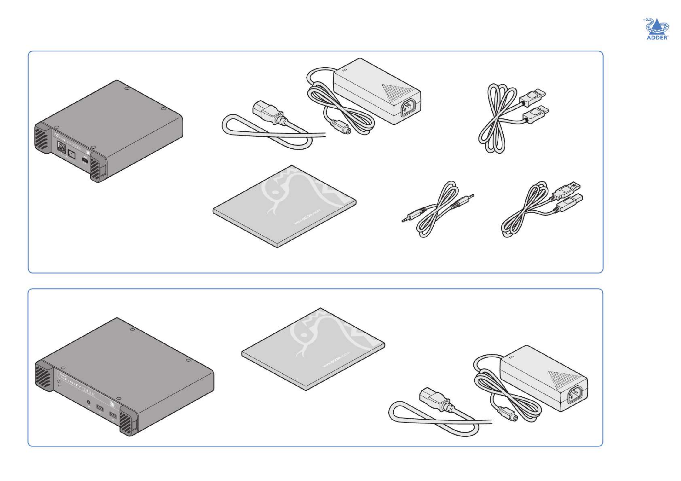
SUPPLIED ITEMS
1x Audio cable 2m
(3.5mm stereo jacks)
ALIF2100 TX package
ALIF2100 RX package
Information wallet
containing:
Four self-adhesive rubber feet
Quick start guide
Safety document
Information wallet
containing:
Four self-adhesive rubber feet
Quick start guide
Safety document
ALIF2100 TX unit
ALIF2100 RX unit
1x USB cable 2m (type A to B)
Part number: VSC24
Power adapter with
locking connector
and country-specic
power cord
Power adapter with
locking connector
and country-specic
power cord
2x video cables
ALIF 2102: DisplayPort™ 2m
ALIF 2122: DisplayPort™ 2m
ALIF 2124: HDMI® 1.5m


INSTALLATION
11
CONFIGURATIONOPERATION
FURTHER
INFORMATION
INDEX
OPTIONAL EXTRAS
Audio cable 2m
(3.5mm stereo jacks)
Part number: VSC22
USB cable 2m (type A to B)
Part number: VSC24
1GbE single mode ber SFP module
Part number: SFP-SM-LC
1GbE multi mode ber SFP module
Part number: SFP-MM-LC
Please refer to the table in Appendix E for
information about ber modules and cables.
Replacement power adapter
with locking connector
Part number: PSU-IEC-12VDC-1.5A
Country-specic power cords
CAB-IEC-AUS (Australia)
CAB-IEC-EURO (Central Europe)
CAB-IEC-UK (United Kingdom)
CAB-IEC-USA (United States)
CAB-IEC-JP (Japan)
CAB-IEC-CN (China)
DisplayPort™ video cable 2m
Part number: VSCD18
19” (1U) rack-mount shelf for
dual ALIF2100 receiver units
Part number: RMK15
Copper SFP module for 1GbE
Part number: SFP-CATX-RJ45
19” (1U) rack-mount shelf for
triple ALIF2100 transmitter units
Part number: RMK17
Rack mount blanking plate
Part number: RMK17-BP
HDMI® cable 1.5m
Part number: VSCD15
DisplayPort™ to HDMI®
video cable 2m
Part number: VSCD19


12
INSTALLATIONCONFIGURATIONOPERATION
FURTHER
INFORMATION
INDEX
MOUNTING
Please see Appendix F for details about mounting options for the ALIF units.
IMPORTANT: When mounting the ALIF units (and their power adapters),
ensure that the vents are not obscured and that there is sufcient airow.
The operating temperature range is 0 to 40ºC (32 to 104ºF) and must not
be exceeded.
Installation
CONNECTIONS
Installation involves linking the ALIF TX unit to various ports on the host computer, while
the ALIF RX unit is attached to your peripherals (collectively known as the :Console)
Click a connection to see details
IMPORTANT: When using an ADDERLink® INFINITY Management box to
congure ALIF units, it is vital that all ALIF units that you wish to locate and control
are set to their factory default settings. Otherwise they will not be located by the
AIM server. If necessary, perform a factory reset on each ALIF unit.
Please also see Appendix B - Tips for success when networking ALIF units
Note: RS232
connections are
supported when
USB/serial adapters
are used.
Suitable for installation in Information
Technology Rooms in accordance with
Article 645 of the National Electrical
Code and NFPA 75.
Peut être installé dans des salles de
matériel de traitement de l’information
conformément à l’article 645 du
National Electrical Code et à la NFPA 75.


13
INSTALLATIONCONFIGURATIONOPERATION
FURTHER
INFORMATION
INDEX
TX video links
The TX unit supports either a single video
connection at up to 2560x1600@60Hz
or two connections, each up to
1920x1200@60Hz.
Note: ALIF1102 and ALIF1104 transmitters
support a single display only.
Note: ALIF1104 and ALIF2124 transmitters do
not support either the CEC or HDCP protocols.
2 Connect the plug at the other end of
the cable(s) to the corresponding video
output socket(s) of the host computer.
To make video links
1 Connect your digital video link cable(s) to the DisplayPort™/
HDMI® socket(s) on the TX unit rear panel:
To secondary
video output
port
To primary
video output
port
TX audio links
By default the TX unit supports
digital audio via its USB
connection. Alternatively, it can
use digital audio from the video
connection(s) or analog audio
via the 3.5mm jack. See
Appendix
B - Support for analog and digital
audio for details.
Analog audio output
from host computer
To make an analog audio link
1 Connect an audio link cable between the 3.5mm
analog audio jack on the TX unit rear panel and
the speaker output socket of the host computer.
To secondary
video output
port
To primary
video output
port
ALIF2102 and ALIF2122
(DisplayPort™) models
ALIF2124
(HDMI®) models
Note: ALIF1102 and
ALIF1104 transmitters
use video port 1 only.

15
INSTALLATIONCONFIGURATIONOPERATION
FURTHER
INFORMATION
INDEX
TX power in
Each unit is supplied with a power
adapter and country-specic power
cord. The supplied power adapter uses
a locking-type plug to help prevent
accidental disconnection; please follow
the instructions shown on the right
when disconnecting a power adapter.
To connect the power adapter
1 Attach the output plug of the supplied
power adapter to the power input
socket on the right side of the rear
panel. As you insert the plug, pull back
slightly on the outer body to assist
the locking mechanism until the plug
is fully inserted.
2 Insert the IEC connector of the supplied country-specic
power cord to the socket of the power adapter.
3 Connect the power cord to a nearby mains supply socket.
To disconnect the power adapter
1 Isolate the power adapter from the mains
supply.
2 Grasp the outer body of the power adapter
plug where it connects with the node.
3 Gently pull the body of the outer plug away
from the node. As the body of the plug
slides back, it will release from the socket
and you can fully withdraw the whole plug.
IMPORTANT: Please read and adhere to the electrical safety information
given within the Safety information booklet provided with this product. In
particular, do not use an unearthed power socket or extension cable.
Note: The unit and the power adapter generate heat when in operation and will become
warm to the touch. Do not enclose them or place them in locations where air cannot circulate
to cool the equipment. Do not operate the equipment in ambient temperatures exceeding
40 degrees Celsius. Do not place the products in contact with equipment whose surface
temperature exceeds 40 degrees Celsius.
From the
power adapter
Gently pull back the plug outer
body to release the lock
19
INSTALLATIONCONFIGURATIONOPERATION
FURTHER
INFORMATION
INDEX
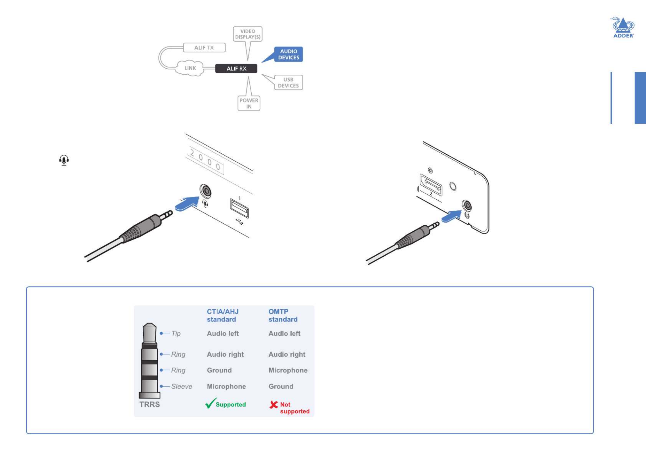
RX audio devices
The RX unit can support headphones
via its front panel jack socket. On the
rear panel a line out jack socket can
be used to drive powered speakers. A
USB link must be made between the
TX unit and the host computer for
audio to operate.
To connect headphones and/or headsets
1 Connect your chosen audio
device to the 3.5mm socket
labeled on the front
panel. Please see below for a
compatibility list.
To
headphones/
headset
Supported devices
All standard headphones and some headsets are directly supported, others require
a suitable converter. It can be difcult to distinguish different headset standards,
however, some (but not all) CTIA/AHJ devices use white dividers on their jack plugs.
Supported
• Stereo headphones - Yes
• Mono microphone – Supported when used with an adapter
• CTIA/AHJ-compliant headset with mic - Yes
• CTIA/AHJ-compliant adapter with mic and headphones plugged in - Yes
Not supported
• OMTP-compliant headset with mic – Not supported directly
• OMTP-compliant adapter with headset plugged in – Not supported directly
Headphone, headset and microphone support
The combined jack socket can
accommodate any standard
stereo headphones; it can
also support headsets which
conform to the CTIA/AHJ
standard. The lesser-used
OMTP standard is not directly
supported as its microphone
and ground connections
are swapped. If used, the
audio may be distorted and/
or the mic will not operate.
Suitable OMTP to CTIA/AHJ
converters are available.
To connect amplied speakers
1 Connect your speakers to
the 3.5mm line out socket
on the rear panel.
To speakers
Produkt Specifikationer
| Mærke: | Adder |
| Kategori: | bryter |
| Model: | Link INFINITY 1104T |
Har du brug for hjælp?
Hvis du har brug for hjælp til Adder Link INFINITY 1104T stil et spørgsmål nedenfor, og andre brugere vil svare dig
bryter Adder Manualer

14 Januar 2025
14 Januar 2025
14 Januar 2025
14 Januar 2025
26 December 2024
26 December 2024
25 December 2024
25 December 2024
25 December 2024
25 December 2024
bryter Manualer
- bryter QNAP
- bryter CyberPower
- bryter Hager
- bryter Finder
- bryter D-Link
- bryter Yamaha
- bryter TRENDnet
- bryter Digitus
- bryter APC
- bryter LevelOne
- bryter Vemer
- bryter ZyXEL
- bryter Tenda
- bryter Iogear
- bryter Smart-AVI
- bryter InLine
- bryter Lancom
- bryter Suevia
- bryter Advantech
- bryter Televés
- bryter Extron
- bryter Ecler
- bryter DEHN
- bryter Cudy
- bryter Atlona
- bryter Roline
Nyeste bryter Manualer
4 April 2025
29 Marts 2025
9 Marts 2025
27 Februar 2025

22 Februar 2025
22 Februar 2025
19 Februar 2025
19 Februar 2025
3 Februar 2025
1 Februar 2025