Christie Roadster S Plus 22K-J Manual
Læs nedenfor 📖 manual på dansk for Christie Roadster S Plus 22K-J (176 sider) i kategorien Beamer. Denne guide var nyttig for 63 personer og blev bedømt med 4.5 stjerner i gennemsnit af 2 brugere
Side 1/176

J Series
2.0, 2.4 and 3.0 kW
U s e r M a n u a l
020-100707-03


J Series
2.0, 2.4 and 3.0 kW
U s e r M a n u a l
020-100707-03

NOTICES
COPYRIGHT AND TRADEMARKS
Copyright © 2011-2014 Christie Digital Systems USA, Inc. All rights reserved.
All brand names and product names are trademarks, registered trademarks or trade names of their respective holders.
REGULATORY
The product has been tested and found to comply with the limits for a Class A digital device, pursuant to Part 15 of the FCC Rules. These limits
are designed to provide reasonable protection against harmful interference when the product is operated in a commercial environment. The
product generates, uses, and can radiate radio frequency energy and, if not installed and used in accordance with the instruction manual, may
cause harmful interference to radio communications. Operation of the product in a residential area is likely to cause harmful interference in which
case the user will be required to correct the interference at the expense of the user.
This Class A digital apparatus complies with Canadian ICES-003.
Cet appareil numérique de la classe A est conforme à la norme NMB-003 du Canada.
이 기기는 급 으로 전자파적합등록을 한 업무용 (A ) 기기이오니 판매자 또는 사용자는 이점을 가정 주의하시기 바라며 , 외의 지역에서 사용하는 것을
목적으로 합니다 .
GENERAL
Every effort has been made to ensure accuracy, however in some cases changes in the products or availability could occur which may not be
reflected in this document. Christie reserves the right to make changes to specifications at any time without notice. Performance specifications
are typical, but may vary depending on conditions beyond the control of Christie such as maintenance of the product in proper working
conditions. Performance specifications are based on information available at the time of printing. Christie makes no warranty of any kind with
regard to this material, including, but not limited to, implied warranties of fitness for a particular purpose. Christie will not be liable for errors
contained herein or for incidental or consequential damages in connection with the performance or use of this material.
The product is designed and manufactured with high-quality materials and components that can be recycled and reused. This symbol
means that electrical and electronic equipment, at their end-of-life, should be disposed of separately from regular waste. Please dispose of
the product appropriately and according to local regulations. In the European Union, there are separate collection systems for used
electrical and electronic products. Please help us to conserve the environment we live in!
Canadian manufacturing facility is ISO 9001 and 14001 certified.
GENERAL WARRANTY STATEMENTS
For complete information about the Christie limited warranty, please contact your Christie dealer. In addition to the other limitations that may be
specified in the Christie limited warranty, the warranty does not cover:
a. Damage occurring during shipment, in either direction.
b. Projector lamps (See the separate Christie lamp program policy).
c. Damage caused by use of a projector lamp beyond the recommended lamp life, or use of a lamp supplied by a supplier other than Christie.
d. Problems caused by combination of the product with non-Christie equipment, such as distribution systems, cameras, video tape recorders,
etc., or use of the product with any non-Christie interface device.
e. Damage caused by misuse, improper power source, accident, fire, flood, lightning, earthquake or other natural disaster.
f. Damage caused by improper installation/alignment, or by product modification, if by other than a Christie authorized repair service
provider.
g. For LCD projectors, the warranty period specified applies only where the LCD projector is in “normal use.” “Normal use” means the LCD
projector is not used more than 8 hours a day, 5 days a week. For any LCD projector where “normal use” is exceeded, warranty coverage
under this warranty terminates after 6000 hours of operation.
h. Failure due to normal wear and tear.
PREVENTATIVE MAINTENANCE
Preventative maintenance is an important part of the continued and proper operation of your product. Please see the Maintenance section for
specific maintenance items as they relate to your product. Failure to perform maintenance as required, and in accordance with the maintenance
schedule specified by Christie, will void the warranty.

Table of Contents
J Series 2.0, 2.4 and 3.0 kW User Manual i
020-100707-03 Rev. 1 (02-2014)
1: Introduction
1.1 Labels and Marking .....................................................................................................................1-1
1.1.1 Typographical Notations......................................................................................................1-1
1.2 Purchase Record and Service Contacts .......................................................................................1-2
1.3 Projector Overview......................................................................................................................1-2
1.3.1 How the Projector Works ....................................................................................................1-2
1.3.2 User Interface Overview......................................................................................................1-2
1.3.3 List of Components..............................................................................................................1-3
1.3.4 Key Features ........................................................................................................................1-3
1.4 Safety Warnings and Guidelines .................................................................................................1-4
1.4.1 General Precautions .............................................................................................................1-4
1.4.2 AC/Power Precautions.........................................................................................................1-5
1.4.3 Lamp Precautions ................................................................................................................1-5
2: Installation and Setup
2.1 Projector Quick Setup and Installation........................................................................................2-1
2.1.1 Install a Projection Lens ......................................................................................................2-1
2.1.2 Position the Projector...........................................................................................................2-3
2.1.3 Connect a Source .................................................................................................................2-3
2.1.4 Connect the Line Cord.........................................................................................................2-3
2.1.5 Power up ..............................................................................................................................2-5
2.1.6 Select a Source.....................................................................................................................2-5
2.1.7 Adjust the Image..................................................................................................................2-6
2.2 Detailed Setup and Installation....................................................................................................2-6
2.2.1 About the Projector..............................................................................................................2-6
2.2.2 Installation Considerations ..................................................................................................2-8
2.2.3 Front Screen Installations ....................................................................................................2-9
2.2.4 Rear Screen Installations .....................................................................................................2-9
2.2.5 Screen Size...........................................................................................................................2-9
2.2.6 Ambient Lighting.................................................................................................................2-10
2.2.7 Ventilation ...........................................................................................................................2-10
2.2.8 Other Considerations ...........................................................................................................2-10
2.3 Projector Position ........................................................................................................................2-10
2.3.1 Throw Distance....................................................................................................................2-10
2.3.2 Vertical and horizontal position...........................................................................................2-11
2.4 Lifting, Hoisting, and Stacking....................................................................................................2-14
2.4.1 Lifting Guidelines ................................................................................................................2-14
2.4.2 Hoisting Guidelines .............................................................................................................2-15
2.4.3 Hoisting Procedure ..............................................................................................................2-16
2.4.4 Stacking Procedure ..............................................................................................................2-16
2.4.5 Alignment Procedure ...........................................................................................................2-19
2.4.6 Mounting..............................................................................................................................2-20
2.4.7 Adjusting Projector Height/Tilt ...........................................................................................2-20
2.4.8 Basic Optical Alignment......................................................................................................2-21
2.4.9 Advanced Optical Alignment ..............................................................................................2-22

ii J Series 2.0, 2.4 and 3.0 kW User Manual
020-100707-03 Rev. 1 (02-2014)
Table of Contents
2.4.10 Powering Down..................................................................................................................2-23
2.5 Connect Communications............................................................................................................2-24
2.5.1 Remote Keypads ..................................................................................................................2-24
2.5.2 Serial Port Connections........................................................................................................2-24
2.5.3 Connect RS-232 ...................................................................................................................2-24
2.5.4 Connect RS-422 ...................................................................................................................2-25
2.5.5 Ethernet Communications....................................................................................................2-26
2.5.6 Connect Multiple Projectors ................................................................................................2-26
2.5.7 Separate Networks ...............................................................................................................2-27
2.5.8 Communicate to all Ports.....................................................................................................2-28
2.5.9 System Integration - GPIO Connector .................................................................................2-28
2.5.10 Configuring the GPIO........................................................................................................2-29
2.6 Projector Communications ..........................................................................................................2-30
2.6.1 Status LEDs..........................................................................................................................2-30
2.7 Connect Sources ..........................................................................................................................2-31
2.7.1 LEDs ....................................................................................................................................2-31
2.7.2 Twin HDMI Input Card .......................................................................................................2-31
2.7.3 Analog BNC Input Card ......................................................................................................2-32
2.7.4 Dual 3G/HD/SD-SDI Input Card.........................................................................................2-32
2.7.5 Dual Link DVI Input Card ...................................................................................................2-32
2.7.6 Video Decoder Input Card ...................................................................................................2-33
2.7.7 DMXC Interface Card..........................................................................................................2-33
2.7.8 Twin DisplayPort Input Card...............................................................................................2-34
2.7.9 Connect Tiled Projectors......................................................................................................2-34
3: Operation
3.1 How to Use the Remote Keypad or Built-In Keypad ..................................................................3-1
3.1.1 Guide to Keypads.................................................................................................................3-1
3.1.2 Remote Keypad....................................................................................................................3-2
3.1.3 Wired Remote ......................................................................................................................3-4
3.1.4 Built-in Keypad....................................................................................................................3-4
3.1.5 Overview of LED and Key States........................................................................................3-4
3.1.6 Remote Keypad Commands.................................................................................................3-5
3.2 Navigating the Menus..................................................................................................................3-9
3.2.1 Main Menu ...........................................................................................................................3-9
3.2.2 Online Help ..........................................................................................................................3-10
3.2.3 The Global Icon ...................................................................................................................3-10
3.2.4 How to Use Slide Bars and Other Controls .........................................................................3-10
3.2.5 Edit Text...............................................................................................................................3-11
3.3 Using Inputs and Channels ..........................................................................................................3-12
3.3.1 How to Select an Input Or a Channel ..................................................................................3-13
3.3.2 Create a New Channel..........................................................................................................3-14
3.3.3 Using A Channel..................................................................................................................3-14
3.3.4 Channel Setup Menu............................................................................................................3-15
3.4 Adjusting the Image.....................................................................................................................3-18
3.5 Size and Position Menu ...............................................................................................................3-19

Table of Contents
J Series 2.0, 2.4 and 3.0 kW User Manual iii
020-100707-03 Rev. 1 (02-2014)
3.5.1 Resize Presets ......................................................................................................................3-19
3.5.2 Size.......................................................................................................................................3-20
3.5.3 Vertical Stretch ....................................................................................................................3-21
3.5.4 Pixel Track...........................................................................................................................3-21
3.5.5 Pixel Phase...........................................................................................................................3-21
3.5.6 H-Position ............................................................................................................................3-21
3.5.7 V-Position ............................................................................................................................3-21
3.5.8 Keep Aspect On Auto Setup ................................................................................................3-21
3.5.9 Blanking - Submenu ............................................................................................................3-22
3.6 Image Settings Menu ...................................................................................................................3-22
3.6.1 Contrast................................................................................................................................3-23
3.6.2 Brightness ............................................................................................................................3-23
3.6.3 Yellow Notch Filter (YNF)..................................................................................................3-23
3.6.4 Color Space..........................................................................................................................3-23
3.6.5 Video Options - Submenu ..3-23..................................................................................................
3.6.6 Input Levels - Submenu.......................................................................................................3-25
3.6.7 Advanced Image Settings - Submenu..................................................................................3-27
3.6.8 Gamma Settings - Submenu ................................................................................................3-28
3.6.9 Detail Settings......................................................................................................................3-29
3.6.10 Noise Reduction Settings...................................................................................................3-29
3.6.11 Color Settings ....................................................................................................................3-29
3.7 Optical Aperture ..........................................................................................................................3-30
3.8 Aperture Manual Adjustment ......................................................................................................3-30
3.9 Configuration - Adjust System Parameters and Advanced Controls ..........................................3-31
3.9.1 Language..............................................................................................................................3-31
3.9.2 Output Options Card - Submenu .........................................................................................3-31
3.9.3 Lens Settings - Submenu .....................................................................................................3-32
3.9.4 Power Management - Submenu...........................................................................................3-32
3.9.5 Date And Time - Submenu ..................................................................................................3-33
3.9.6 Menu Preferences - Submenu ..............................................................................................3-33
3.9.7 Communications - Submenu................................................................................................3-34
3.9.8 Serial Options - Submenu ....................................................................................................3-34
3.9.9 Ethernet Settings - Submenu................................................................................................3-35
3.9.10 DMX / ArtNET - Submenu ...............................................................................................3-35
3.9.11 SNMP - Submenu ..............................................................................................................3-37
3.9.12 Geometry And Color - Submenu .......................................................................................3-39
3.9.13 Geometry Correction - Submenu.......................................................................................3-39
3.9.14 Brightness Uniformity - Submenu.....................................................................................3-41
3.9.15 Edge Blending - Submenu .................................................................................................3-43
3.9.16 Advanced Edge Blending - Submenu................................................................................3-44
3.9.17 Color Adjustments By X/Y - Submenu .............................................................................3-45
3.9.18 Color Saturation - Submenu ..............................................................................................3-46
3.9.19 Black Level Blending - Submenu......................................................................................3-47
3.9.20 Default Color Adjustments and Default Color Adjustment with YNF .............................3-47
3.9.21 Tiling Setup - Submenu .....................................................................................................3-47
3.9.22 Diagnostics And Calibration - Submenu ...........................................................................3-48

iv J Series 2.0, 2.4 and 3.0 kW User Manual
020-100707-03 Rev. 1 (02-2014)
Table of Contents
3.9.23 Service - Submenu .............................................................................................................3-49
3.9.24 Option Card Settings - Submenu .......................................................................................3-49
3.10 Lamp Menu................................................................................................................................3-50
3.10.1 Lamp Mode ........................................................................................................................3-50
3.10.2 Power .................................................................................................................................3-50
3.10.3 Intensity..............................................................................................................................3-50
3.10.4 Warn When Lamp Reaches (Hours) ..................................................................................3-50
3.10.5 Lamp S/N ...........................................................................................................................3-50
3.10.6 Change Lamp - Submenu...................................................................................................3-51
3.10.7 Lamp History .....................................................................................................................3-51
3.11 Input Switching and PIP Menu ..................................................................................................3-51
3.11.1 Main Input..........................................................................................................................3-51
3.11.2 PIP Input ............................................................................................................................3-51
3.11.3 Swap Main and PIP Inputs.................................................................................................3-51
3.11.4 PIP Enable .........................................................................................................................3-51
3.11.5 PIP Windows Options - Submenu .....................................................................................3-51
3.11.6 PIP Size and Position - Submenu.......................................................................................3-52
3.11.7 PIP Image Settings - Submenu...........................................................................................3-52
3.11.8 Fade Time ..........................................................................................................................3-52
3.11.9 Frame Locking ...................................................................................................................3-52
3.11.10 Auto Input Searching .......................................................................................................3-52
3.11.11 HDMI Output Loop Source .............................................................................................3-52
3.11.12 Standby Active Loop-through..........................................................................................3-53
3.12 Status..........................................................................................................................................3-53
3.13 Using Multiple Projectors..........................................................................................................3-53
3.13.1 Match Colors in Multiple Screens .....................................................................................3-53
3.13.2 Preliminary Calibration......................................................................................................3-53
3.13.3 Color Adjustment Procedure..............................................................................................3-54
3.13.4 Use the Color Saturation Menu for Color Match...............................................................3-56
3.14 Remote Control of the Projector ................................................................................................3-56
3.15 Alarm Conditions.......................................................................................................................3-56
4: Web User Interface
4.1 Logging On ..................................................................................................................................4-1
4.2 Navigate the Web User Interface.................................................................................................4-2
4.2.1 Help Text..............................................................................................................................4-2
4.2.2 Basic Operation....................................................................................................................4-3
4.2.3 Main Tabbed Page - General ...............................................................................................4-3
4.2.4 Main Tabbed Page - Status ..................................................................................................4-3
4.2.5 Main Tabbed Page - Lens ....................................................................................................4-4
4.2.6 Tools Tabbed Page - Virtual OSD .......................................................................................4-4
4.2.7 Admin Tabbed Page - System..............................................................................................4-6
4.2.8 Admin Tabbed Page - Users ................................................................................................4-8
4.2.9 Advanced Tabbed Pa 9ge - RTE.............................................................................................4-

Table of Contents
J Series 2.0, 2.4 and 3.0 kW User Manual v
020-100707-03 Rev. 1 (02-2014)
5: Maintenance
5.1 Lamp and Filter Replacement......................................................................................................5-1
5.1.1 Lamp Replacement Procedure .............................................................................................5-1
5.1.2 Filter Replacement Procedure..............................................................................................5-4
5.2 Replacing the Projection Lens.....................................................................................................5-5
5.3 Cleaning the Lens ........................................................................................................................5-6
5.4 Liquid Coolant Maintenance .......................................................................................................5-7
5.4.1 Check Liquid Coolant Level................................................................................................5-7
5.4.2 Refilling Liquid Coolant Module ........................................................................................5-7
5.4.3 Remove the Liquid Coolant Module from the Projector (Optional) ...................................5-8
5.5 Power Cord and Attachments......................................................................................................5-8
5.6 Ventilation ...................................................................................................................................5-9
5.7 Replacing Keypad Batteries ........................................................................................................5-9
5.8 Servicing Requirements...............................................................................................................5-9
6: Troubleshooting
6.1 Power...........................................................................................................................................6-1
6.1.1 Projector Does Not Power ON.............................................................................................6-1
6.2 Lamp............................................................................................................................................6-1
6.2.1 Lamp Does Not Ignite..........................................................................................................6-1
6.2.2 Lamp Suddenly Turns OFF .................................................................................................6-2
6.2.3 Flicker, Shadows Or Dimness .............................................................................................6-2
6.3 LCD .............................................................................................................................................6-2
6.3.1 Blank Screen, No Menu Display .........................................................................................6-2
6.4 Remote Keypad ...........................................................................................................................6-2
6.4.1 Remote Keypad Does Not Seem to Work ...........................................................................6-2
6.5 OSD .............................................................................................................................................6-3
6.5.1 The OSD Menu Does Not Display ......................................................................................6-3
6.6 Ethernet........................................................................................................................................6-3
6.6.1 Can Not Establish Communication with Projector..............................................................6-3
6.7 Displays .......................................................................................................................................6-3
6.7.1 The Projector is ON but There is No Display......................................................................6-3
6.7.2 Severe Motion Artifacts.......................................................................................................6-3
6.7.3 Image Appears ‘Squeezed’ or Vertically Stretched into Center of Screen..........................6-3
6.7.4 The Display is Jittery or Unstable........................................................................................6-4
6.7.5 The Display is Faint.............................................................................................................6-4
6.7.6 The Upper Portion of the Display is Waving, Tearing or Jittering......................................6-4
6.7.7 Portions of the Display are Cut Off or Warped to the Opposite edge .................................6-4
6.7.8 Display Appears Compressed (Vertically Stretched) ..........................................................6-4
6.7.9 Data is Cropped from Edges................................................................................................6-4
6.7.10 Display Quality Appears to Drift from Good to Bad, Bad to Good ..................................6-4
6.7.11 Display Suddenly Freezes..................................................................................................6-4
6.7.12 Colors in the Display are Inaccurate..................................................................................6-5
6.7.13 Display is Not Rectangular ................................................................................................6-5
6.7.14 Display is “Noisy” .............................................................................................................6-5

vi J Series 2.0, 2.4 and 3.0 kW User Manual
020-100707-03 Rev. 1 (02-2014)
Table of Contents
6.8 Web Interface...............................................................................................................................6-5
6.8.1 After a Projector Software Upgrade, The Web Pages Do Not Display Correctly ...............6-5
6.8.2 A Backup Or Interrogator File Cannot Be Saved ................................................................6-6
7: Specifications
7.1 Image Performance ......................................................................................................................7-1
7.1.1 Pixel Format ........................................................................................................................7-1
7.1.2 Brightness (ANSI Lumens) .................................................................................................7-1
7.1.3 Contrast ................................................................................................................................7-1
7.1.4 Luminance Uniformity.........................................................................................................7-1
7.1.5 Grayscale/Color Resolution .................................................................................................7-1
7.1.6 Gamma .................................................................................................................................7-2
7.1.7 Color Temperature ...............................................................................................................7-2
7.1.8 Convergence.........................................................................................................................7-2
7.1.9 Blemishes .............................................................................................................................7-2
7.1.10 Pixel Defects ......................................................................................................................7-3
7.2 Feature Set ...................................................................................................................................7-3
7.2.1 Airflow ................................................................................................................................7-3
7.2.2 Air Filters (Optional) ...........................................................................................................7-3
7.2.3 Dust Sealing .........................................................................................................................7-3
7.2.4 ILS (Intelligent Lens System) ..............................................................................................7-3
7.2.5 Projection Lens Compatibility .............................................................................................7-3
7.2.6 Automatic Fans ....................................................................................................................7-4
7.2.7 Constant Lamp Output Management ...................................................................................7-4
7.2.8 Shutter .................................................................................................................................7-4
7.2.9 Lamp ....................................................................................................................................7-4
7.2.10 Status LED .........................................................................................................................7-5
7.2.11 Electronics/SW ..................................................................................................................7-5
7.3 Image Processor Performance......................................................................................................7-6
7.4 Input (Source Signal) Compatibility ...........................................................................................7-6
7.4.1 Analog (Only) Input.............................................................................................................7-6
7.4.2 Twin HDMI Input ................................................................................................................7-6
7.4.3 Dual Link DVI Input............................................................................................................7-7
7.4.4 Video Decoder Input............................................................................................................7-7
7.4.5 Dual 3G/HD/SD-SDI ...........................................................................................................7-7
7.4.6 DisplayPort Input .................................................................................................................7-7
7.5 Control Signal Compatibility ......................................................................................................7-8
7.5.1 Projector Control..................................................................................................................7-8
7.5.2 Control Receiver ..................................................................................................................7-8
7.5.3 RS-232 .................................................................................................................................7-8
7.5.4 RS-422 .................................................................................................................................7-8
7.5.5 Ethernet ................................................................................................................................7-8
7.5.6 USB 2.0 Device Port............................................................................................................7-8
7.5.7 GPIO ....................................................................................................................................7-9
7.5.8 DMX512 Interface ...............................................................................................................7-9
7.5.9 Built-In Keypad and Display ...............................................................................................7-9

Table of Contents
J Series 2.0, 2.4 and 3.0 kW User Manual vii
020-100707-03 Rev. 1 (02-2014)
7.5.10 Convenience Light.............................................................................................................7-9
7.6 Power Requirements....................................................................................................................7-9
7.6.1 Lamp Specification ..............................................................................................................7-10
7.7 Physical Specifications ................................................................................................................7-10
7.7.1 Size.......................................................................................................................................7-10
7.7.2 Adjustment...........................................................................................................................7-10
7.7.3 Weight..................................................................................................................................7-10
7.8 Reliability and Serviceability ......................................................................................................7-10
7.8.1 Reliability.............................................................................................................................7-10
7.8.2 Serviceability .......................................................................................................................7-11
7.9 Environment ................................................................................................................................7-11
7.9.1 Temperature/Humidity/Altitude ..........................................................................................7-11
7.10 Accessories and Service Components .......................................................................................7-11
7.11 Regulatory .................................................................................................................................7-12
7.11.1 Safety .................................................................................................................................7-12
7.11.2 Electro-Magnetic Compatibility ........................................................................................7-12
7.11.3 Environmental....................................................................................................................7-12
7.11.4 Marking..............................................................................................................................7-13
A: Menu Tree
A.1 J Series Menu Tree .....................................................................................................................A-1
B: DMX / ArtNET
B.1 DMX and Real Time Events.......................................................................................................B-1
B.1.1 What is DMX? ....................................................................................................................B-1
B.1.2 What is Real Time Events? .................................................................................................B-1
B.1.3 Lens Control ...B-1Limitations .................................................................................................
B.2 DMX Channel Setup...................................................................................................................B-2
B.2.1 J Series Setup Personality ...................................................................................................B-3
B.2.2 J Series Show Personality ...................................................................................................B-6
B.2.3 J Series Nitro VIP Projector Yoke Personality ...................................................................B-8


J Series 2.0, 2.4 and 3.0 kW User Manual 1-1
020-100707-03 Rev. 1 (02-2014)
1 Introduction
Every effort has been made to ensure the information in this document is accurate and reliable; however, due to
constant research the information in this document is subject to change without notice.
USERS/OPERATORS: This manual is intended for trained users operating professional high-brightness
projection systems. Such users may also be trained to replace the lamp and air filter, but cannot install the
projector or perform any service functions on the projector.
SERVICE: Only Christie accredited technicians knowledgeable about all potential hazards associated with
high voltage, ultraviolet exposure and high temperatures generated by the lamp and associated circuits are
authorized to: 1) assemble/install the projector and 2) perform service functions inside the projector.
DISCLAIMER: Christie Digital Systems assumes no responsibility for omissions or inaccuracies. Updates to
this document are published regularly, as required. Please contact Christie Digital Systems for availability.
1.1 Labels and Marking
Observe and follow any warnings and instructions marked on the projector.
Indicates a hazardous situation which, if not avoided, will result in death or
serious injury. This signal word is to be limited to the most extreme situations.
Indicates a hazardous situation which, if not avoided, could result in death or
serious injury.
Indicates a hazardous situation which, if not avoided, could result in minor or
moderate injury. It may also be used without the safety alert symbol as an
alternative to “NOTICE”.
1.1.1 Typographical Notations
The following notations are used throughout this manual:
• Keypad commands and PC keystrokes appear in bold, small caps, such as POWER, , INPUT ENTER and so on.
• References to areas within the current document appear italicized and underlined. When viewed online, the
text appears in blue indicating a direct link to that section. For example, Section 2 Installation and Setup.
• References to other documents appear italicized and blue. When viewed online, the text appears in blue
indicating a direct link to that section. For example, refer to Service Manual.
• References to software menus and available options appear bold, such as Main menu, and available options
appear italicized, such as Preferences.
• User input or messages that appear on screen, in status display units or other control modules appear in
Courier font. For example. “No Signal Present”, Login: christiedigital.
• Error codes, LED status codes appear bold, for example, LP, A1, and so on.
• Operational states of modules appear capitalized, such as power ON/OFF.
1-2 J Series 2.0, 2.4 and 3.0 kW User Manual
020-100707-03 Rev. 1 (02-2014)
Section 1: Introduction
1.2 Purchase Record and Service Contacts
Whether the projector is under warranty or the warranty has expired, Christie’s highly trained and extensive
factory and dealer service network is always available to quickly diagnose and correct projector malfunctions.
Complete service manuals and updates are available for all projectors. Should a problem be encountered with
any part of the projector, contact your dealer. In most cases, servicing is performed on site. If you have
purchased the projector, fill out the information below and keep with your records.
* The serial number can be found on the license label located on the back of the projector.
1.3 Projector Overview
The J Series is a family of high resolution video/graphics 3 chip 1080p HD, SXGA+, WUXGA and WXGA
projectors, see Table 1.2 J Series Projectors for specific models. These projectors are based on next
generation DLP™ technology provided by Texas Instruments.
1.3.1 How the Projector Works
The projector accepts data/graphics and video input signals for projection onto front or rear screens. Light is
generated by a Xenon lamp, then modulated by three Digital Micro-mirror Device (DMD) panels that provide
digitized red, green or blue color information. Light from the ON pixels of each panel is reflected, converged
and then projected to the screen through a single front lens, where all pixels are perfectly superimposed as a
sharp full-color image.
1.3.2 User Interface Overview
The projector can be controlled using a menu system displayed on the image. The menu system can be
controlled by an IR remote, wired remote or through the built-in keypad. The LCD screen and built-in keypad
allow some functions to be controlled without the need of an OSD display, and provide a quickly accessible
interface to view error reporting. The functions on the OSD can also be controlled using the Christie Serial
Protocol, using a serial or Ethernet connection to the projector. The Web interface provides access to the menu
system as a Virtual OSD (On-screen display) and to features that maintain the software and settings.
Dealer:
Dealer or Christie Sales/Service Contact Phone Number:
Projector Serial Number*:
Purchase Date:
Installation Date:
Table 1.1 Ethernet Settings
Default Gateway:
DNS Server:
Projector DLP Address:
Projector Mgmt IP Address:
Subnet Mask:
Section 1: Introduction
J Series 2.0, 2.4 and 3.0 kW User Manual 1-3
020-100707-03 Rev. 1 (02-2014)
1.3.3 List of Components
Ensure the following components were received with the projector:
IR remote keypad (includes two, 1.5V AA batteries and an XLR to mini-stereo cable conversion to wired)
Line cord
Lens Mount Security Screw (M6x10mm long, Qty. 2)
Lens Mount Security Screw (5mm Hex, Qty. 1)
Warranty Card
Web Registration Form
1.3.4 Key Features
• Up to 22,000 lumens
• HD (1080p), SXGA+, or WUXGA resolution
• Xenon lamp with 1900W, 2400W, or 3000W options
• 10-bit image processor electronics with modular design
• Active fan control for minimum noise level
• User interchangeable projection lenses with no-tool mounting
• LiteLOC™ for constant brightness maintenance
• Intelligent Lens System (ILS)
• Motorized lens mount for all models
• Auto-setup feature
• Integrated ChristieNET
• Networking ability through RS-232 and RS-422 connectors
• Status LED display on built-in keypad for easy projector status monitoring
• Control with remote keypad, wired remote, or built-in keypad
• Four input slots for Optional Input Modules
See Section 7 Specifications for a complete list of technical specifications.
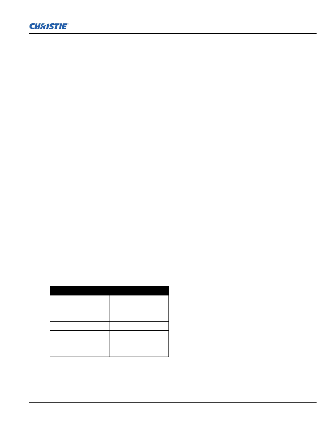
Table 1.2 J Series Projectors
MODEL NAME PART NUMBER
Roadster S+14K-J 132-010113-XX
Roadster HD14K-J 132-011114-XX
Roadster S+18K-J 132-013116-XX
Roadster HD16K-J 132-014117-XX
Roadster S+22K-J 132-016119-XX
Roadster HD20K-J 132-017110-XX
Roadster WU20K-J 132-018111-XX

1-4 J Series 2.0, 2.4 and 3.0 kW User Manual
020-100707-03 Rev. 1 (02-2014)
Section 1: Introduction
1.4 Safety Warnings and Guidelines
1.4.1 General Precautions
HIGH BRIGHTNESS. Never look directly into the projector lens. The extreme
high brightness can cause permanent eye damage.
Always power down the projector and disconnect all power sources before
servicing or cleaning.
FIRE HAZARD. Keep hands, clothes and all combustible material away from
the concentrated light beam of the projector. Position all cables where they
cannot contact hot surfaces or be pulled or tripped over.
In the unlikely event of a lamp explosion, particles may be blown out of the
rear air vents. Keep clear of the exhaust air path during operation. Take
appropriate precautions to shield operators and audience members from lamp
explosion particles.
High leakage current. Earth connection essential before connecting supply.
All installation and maintenance procedures must be performed by a Christie
accredited service technician.
Projector must be operated in an environment that meets operating
specifications, as listed in Section 7 Specifications.
The American Conference of Governmental Industrial Hygienists (ACGIH)
recommends occupational UV exposure for an 8-hour day to be less than 0.1
microwatts per square centimeters of effective UV radiation. An evaluation of
your workplace is advised to assure employees are not exposed to cumulative
radiation levels exceeding the government guidelines for your area. Be aware
that some medications are known to increase sensitivity to UV radiation.

Section 1: Introduction
J Series 2.0, 2.4 and 3.0 kW User Manual 1-5
020-100707-03 Rev. 1 (02-2014)
1.4.2 AC/Power Precautions
Use only the AC power cord supplied. Do not attempt operation if the AC
supply and cord are not within the specified voltage and power range. See
the license label on the back of the projector or Section 7 Specifications for rated
voltage and power.
The projector is equipped with a 3-wire plug with a grounding pin. This is a
safety feature. If you are unable to insert the plug into the outlet, contact an
electrician to have the outlet replaced. NEVER defeat the safety purpose of
the grounding-type plug.
Do not allow anything to rest on the power cord. Locate the power cord
where persons walking on it or objects rolling over it cannot damage the cord.
1.4.3 Lamp Precautions
Never attempt to access the lamp while the lamp is ON. After turning the
lamp OFF, it is crucial that you wait at least 10 minutes before handling the
lamp. This provides sufficient time for the lamp cooling fans to properly cool
the lamp. For all other precautions critical for safe removal and replacement
of the lamp. High leakage current. Earth connection essential before
connecting supply..


J Series 2.0, 2.4 and 3.0 kW User Manual 2-1
020-100707-03 Rev. 1 (02-2014)
2 Installation and Setup
This section explains how to install, connect and optimize the projector for delivery of superior image quality.
Illustrations are graphical representations only and are provided to enhance the understanding of the written
material.
2.1 Projector Quick Setup and Installation
The following instructions are for those preferring a quick setup. Refer to the remaining subsections for
detailed setup instructions.
Always power down the projector and disconnect all power sources before
servicing or cleaning.
See the Safety Warnings and Guidelines in Section 5 Maintenance.
2.1.1 Install a Projection Lens
The projection lens, shipped separately from the projector, must be installed prior to setting up the projector.
Remove the lens plug from the lens opening in the projector before installing
the lens. Retain the lens plug for projector transportation to protect the
optical components from dust and debris.
IMPORTANT! The lens seals the projector, preventing contaminants from entering the interior of the
projector. Never operate a projector without a lens. Remove the rear lens cap from the lens.
Keep the front lens cap on the lens to protect it during installation.
1. Rotate the lens clamp to the OPEN position, as shown.

2-2 J Series 2.0, 2.4 and 3.0 kW User Manual
020-100707-03 Rev. 1 (02-2014)
Section 2: Installation and Setup
2. Align the lens interface plate with the lens mount. Align the lens electrical connector with the mating
connector on the lens mount. Fully insert the assembly straight into the lens mount opening without
turning. Press using your hand as shown.
NOTE: When installing the lens, ensure that the lens is not inserted at an angle, as this can cause damage.
3. While holding the lens flat against the lens mount, rotate the lens clamp clockwise to lock the lens
assembly in place.
4. Remove the front lens cap.
5. For added stability such as motion applications, fasten the security screws provided with the lens-mount.
NOTE: There are two types of lens plate models.
6. Use a 5mm hex driver to fasten the red security screws provided with the lens mount, or hand tighten the
lens retaining screws attached to the lens.
NOTES: 1) Recommended for heaviest lenses such as 0.73:1 and 1.2:1.
Use of the lens red security screws or the lens retaining screws is required if
the projector is hoisted or installed in an overhead position.

Section 2: Installation and Setup
J Series 2.0, 2.4 and 3.0 kW User Manual 2-3
020-100707-03 Rev. 1 (02-2014)
2.1.2 Position the Projector
2 people are required to safely lift and install the projector.
Place the projector on a sturdy, level surface and position it so that it is perpendicular to the screen at a suitable
distance. The further back the projector is positioned for the screen, the larger the image will be.
To level the projector adjust the 3 feet. With the project the screen the image will or positioned perpendicular to
appear rectangular instead of keystoned.
For more detailed instructions to position the projector, see 2.3 Projector Position.
2.1.3 Connect a Source
The input panel where all source connections are made, is located at the back of the projector. Each input is
clearly labeled for easy identification. Depending on the type of option card installed, connect your source
using the appropriate cable(s), as follows:
•Analog Input Card: Connect 3-, 4-, or 5-wire RGB source to Red/Pr, Green/Y, Blue/Pb, H/C and V using 3,
4 or 5 BNC connectors as required.
•Dual 3G/HD/SD-SDI Input Card: Connect the SDI (Serial Digital Interface) cable to one of the two inputs,
1-IN or 2-IN. Both standard-definition (SD) and high-definition (HD) signals are accepted and automatically
recognized on either input.
•Dual Link DVI Input Card: Connect a single or dual DVI video signal to the DVI-I connector, an analog
video signal to the DVI-I connector or an analog video signal to the VGA connector. The DVI signal may
contain HDCP (High-Bandwidth Digital Content Protection).
•Twin HDMI Input Card: Connect HDMI (High-Definition Multimedia Interface) cable to one of the two
inputs, 1-IN or 2-IN.
•Video Decoder Input Card: Depending on the source you can apply the following;
• Composite video source to 1-CVBS, using a BNC Cable
NOTE: Same signal can be used on 4, 5 or 6 when input is selected as CVBS.
• A component signal on Inputs 4(Pr), 5(Y), 6(Pb) using BNC Connectors.
Grouped as a component input, YPbPr.
• S-Video to one of the two, 2-SVID or 3-SVID using S-Video cable.
• S-Video using two BNC cables, with Luma (Y) connected to 4 (Sy) and Chroma (C) connected to 6 (Sc).
NOTE: Must be grouped as 1 S-Video + 1 CVBS.
•DMX512 Interface Card: Has two 5pin XLR connectors - 1 (input) male and 1 (output) female. If there is
active communications on the DMX512 Interface card the power LED will blink between low intensity and
high intensity.
•Twin DisplayPort Input Card: Accepts DisplayPort 1.1a inputs from one or two DisplayPort sources.
See 2.7 Connect Sources for more details.
2.1.4 Connect the Line Cord
High leakage current. Earth connection essential before connecting supply.
IMPORTANT!Use the line cord provided with the projector, or ensure you are using a line cord, power plug
and socket that meet the appropriate rating standards. Voltage and current requirements are
listed on the license label, located at the back of the projector. This product can be connected
to an IT power distribution system.
To prevent the line cord from inadvertent disconnection, perform one of the following steps:

2-4 J Series 2.0, 2.4 and 3.0 kW User Manual
020-100707-03 Rev. 1 (02-2014)
Section 2: Installation and Setup
For 1900W and 2400W Models:
1. Connect the line cord of the projector to the AC receptacle at the AC inlet of the projector, then push the
wire clip over the plug to retain it, as shown.
For 3000W Model:
1. Remove the locking pin from the bracket surrounding the AC receptacle at the AC inlet of the projector by
pressing down on the button on the end of the locking pin, and then pull upwards on the pin to remove it.
2. Open the cap on the AC plug and line up the slot on the plug with the pin on the receptacle.
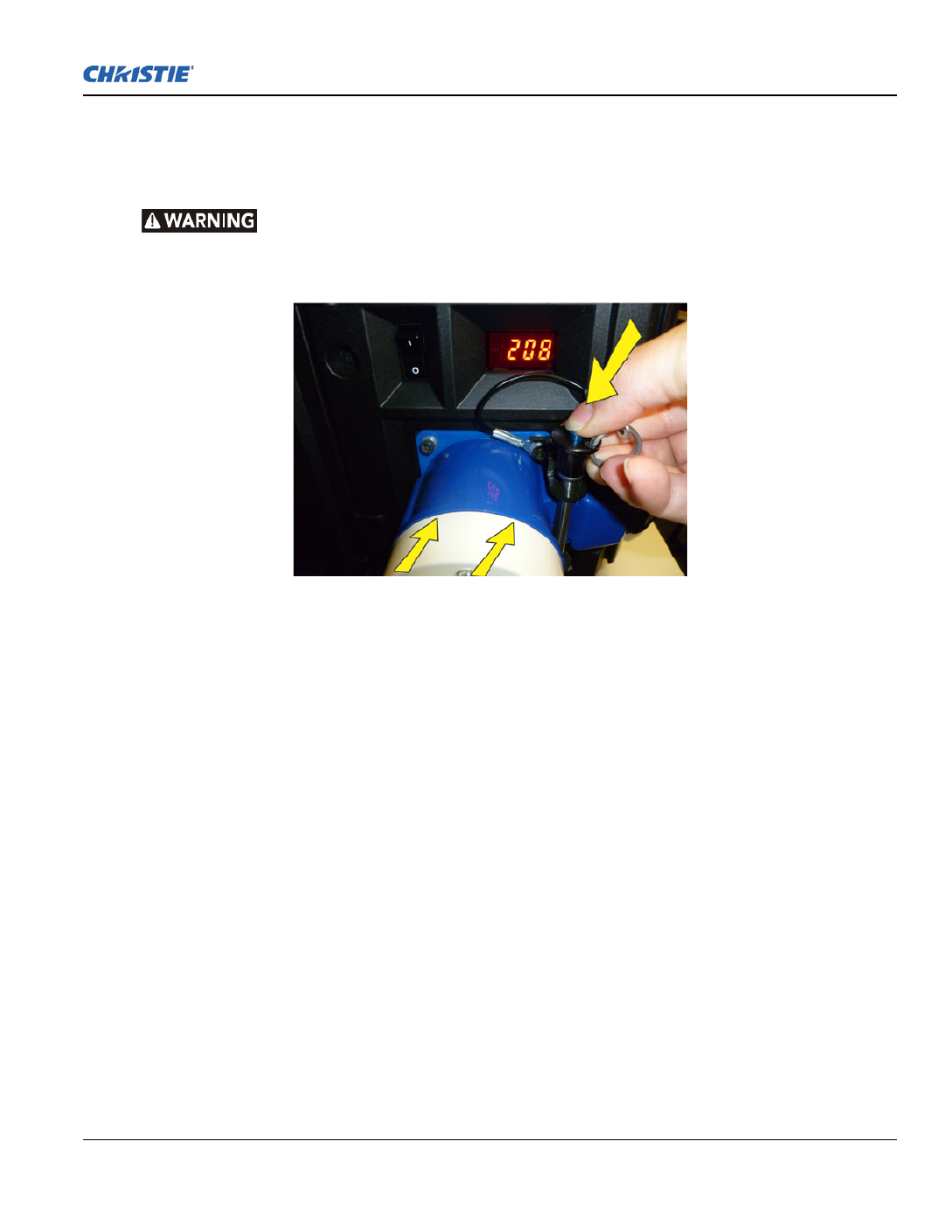
Section 2: Installation and Setup
J Series 2.0, 2.4 and 3.0 kW User Manual 2-5
020-100707-03 Rev. 1 (02-2014)
3. Insert the plug fully on to the receptacle. When fully inserted, the cap on the AC plug will rest against the
side of the projector.
4. Reinsert the locking pin into the bracket surrounding the AC receptacle by pressing down on the button on
the end of the locking pin and insert the pin into the bracket, as shown.
Do not attempt operation if the AC supply and cord is not within the specified
ratings. On power down, wait 5 minutes for the fans to turn OFF before
unplugging the projector. Always switch off the projector before unplugging
the AC line cord.
2.1.5 Power up
After the AC Power has been switched on, the LCD display above the keypad indicates “Please wait” and the
4 LED status indicators at the rear of the projector will be solid amber.
The projector has reached standby and is ready for use when:
• The LCD displays “Standby mode”
• The Status LED is solid amber
• The Lamp LED is off
To turn on the projector, do one of the following:
• Press and hold the power button on either the built-in keypad or the remote control
• Press the power button twice (q keypad or the remote controluickly) on either the built-in
Thereafter; the lamp and fans will power on and a green LED will start scrolling back and forth indicating that
the projector is in warm up mode.
The projector is on and ready to display video when the lamp LED and the status LED are both solid green.
NOTES: 1) See Section 3 Operation for a full description of the status indicators. 2) If the projector has a
stepper motor lens mount installed and the inserted lens has never been calibrated, there will be a short period
where the projector calibrates all of the lens motors (zoom, focus, horizontal, and vertical) by moving them
through their full range of motion.
2.1.6 Select a Source
Press one of the input keys on the remote, or on the built-in keypad to select and display the image for a
connected source.

2-6 J Series 2.0, 2.4 and 3.0 kW User Manual
020-100707-03 Rev. 1 (02-2014)
Section 2: Installation and Setup
2.1.7 Adjust the Image
Adjust the image settings, such as Brightness, Contrast, Gamma, Focus, Zoom etc. using the direct keys on the
remote, or on the built-in keypad. See Section 3 Operation for more details.
2.2 Detailed Setup and Installation
Always power down the projector and disconnect all power sources before
servicing or cleaning.
In the unlikely event of a lamp explosion, particles may be blown out of the
rear air vents. Keep clear of the exhaust air path during operation. Take
appropriate precautions to shield operators and audience members from lamp
explosion particles.
High leakage current. Earth connection essential before connecting supply.
See the Safety Warnings and Guidelines in 1.4 Safety Warnings and Guidelines.
2.2.1 About the Projector
Built-In Keypad
The built-in keypad is located on the side of the projector. Use it similarly to the IR remote to control the
projector. An LCD display is located above the keypad for displaying projector status.
AC Receptacle
The AC receptacle is located above the AC receptacle at the back of the projector. Use this receptacle to plug in
an appropriately rated line cord.

Section 2: Installation and Setup
J Series 2.0, 2.4 and 3.0 kW User Manual 2-7
020-100707-03 Rev. 1 (02-2014)
Adjustable Feet
Located on the underside of the projector are four adjustable feet. Raise or lower these feet when positioning
the projector to ensure it is level on all sides so the displayed image will appear rectangular without any
keystone. See 2.4.7 Adjusting Projector Height/Tilt for instructions on how to adjust the projector feet.
Input Panel
All source connections are made to the input panel located at the back of the projector. Any of the available
optional input cards can be installed in the 4 option card slots. The slots are labelled 1 through 4. All option
cards have LEDs to indicate their status.
Cooling and Air Vents
There are numerous air vents located around the projector. It is important these vents remain unobstructed.
Adequate airflow through the projector will prevent it from overheating.
Lamp Door
The lamp door is located at the rear of the projector, to provide easy access to the lamp module for
replacement. See 5.1.1 Lamp Replacement Procedure. The lamp door is fitted with a safety interlock which
switches the lamp off when the door is opened.
Front and Rear IR Sensors
The two IR sensors located on the projector receive transmissions from the IR remote from up to 100 feet
away. It is important to keep the transmission path to these sensors unobstructed for uninterrupted communica-
tions with the projector. The rear IR sensor is located at the back of the projector between the status LEDs and
the front IR sensor is located next to the projector front nameplate.
Projection Lenses, Lens Mount and Other Features
The projector includes a motorized lens mount that allows automated lens control and adjustment: vertical and
horizontal offsets, zoom and focus.
•Zoom and Focus: There are two internal lens motors that allow for quick motorized adjustment of zoom and
focus. Adjust zoom to fit the displayed image on the screen and adjust focus to improve the clarity of the
image.

2-8 J Series 2.0, 2.4 and 3.0 kW User Manual
020-100707-03 Rev. 1 (02-2014)
Section 2: Installation and Setup
NOTES: 1) The projection lens is shipped separately from the projector. 2) Use the lens cap when
transporting the lens to avoid scratching and damaging the lens, which could affect your displayed image. 3)
Motorized lenses should not be adjusted by hand without first setting them for manual operation, otherwise
the zoom and focus motors may be damaged.
(Set in Menu > Configuration > Lens Settings > Manual Zoom/Focus).
•Lens Offset: The motorized lens mount allows vertical and horizontal offset of the displayed image.
•Shutter: Allows the screen to become absolute black, when in the “closed” state.
2.2.2 Installation Considerations
Proper installation of the projector will ensure the quality of the display. Whether installing a projector
temporarily or permanently, take the following into account to make sure the projector performs optimally.
Choose the installation type that best suits your needs: front or rear screen, portrait mode, floor mount or
inverted mount.
Front Screen / Floor Mount Installations
Front Screen / Inverted Mount (ceiling) Installation
Rear Screen / Floor Mount Installation
Rear Screen / Inverted Mount (ceiling) Installation
ADVANTAGES CONSIDERATIONS
Easy to set up.
Can be moved or changed quickly.
Easy to access.
Shares floor space with audience.
ADVANTAGES CONSIDERATIONS
Does not take up audience space.
Projector is unobtrusive.
Projector cannot be accidentally moved.
Installation is more permanent.
It is more difficult to access the projector.
ADVANTAGES CONSIDERATIONS
Projector is completely hidden.
Projector is easily accessed.
Usually good ambient light rejection.
Requires separate room or enclosure.
Installation cost is usually higher.
ADVANTAGES CONSIDERATIONS
Projector is completely hidden.
Usually good ambient light rejection.
Requires separate room.
Installation cost is usually higher.
More difficult to access projector.

2-10 J Series 2.0, 2.4 and 3.0 kW User Manual
020-100707-03 Rev. 1 (02-2014)
Section 2: Installation and Setup
2.2.6 Ambient Lighting
The high brightness of this projector is well suited for locations where ambient lighting might be considered
less than ideal. A typical room with ceiling lights and windows rarely requires special attention. Contrast ratio
in your images will be reduced if stray light directly strikes the screen. For example, when a shaft of light from
a window or floodlight falls on the image. Images may appear washed out and less vibrant. Avoid or eliminate
stray light sources directed at the screen.
2.2.7 Ventilation
The projector vents and louvers provide ventilation, both for intake and
exhaust. Never block or cover these openings. Do not install the
projector near a radiator or heat register, or within an enclosure. To
ensure adequate airflow around the projector, allow free air exchange to
the projector with a minimum clearance of 25cm (10-inch) on the left,
right and rear sides of the projector from any walls or other
obstructions. Never obstruct the air exchange to the projector.
2.2.8 Other Considerations
Other considerations and tips to improve your installation:
• Keep the ambient temperature constant and below 40°C (104°F). Keep the projector away from heating and/
or air conditioning vents. Changes in temperature may cause drifts in the projector circuitry, which may
affect performance.
• Keep the projector away from devices that radiate electromagnetic energy, such as motors and transformers,
slide projectors, speakers, power amplifiers, elevators, etc.
• Use a screen size appropriate for the venue but not larger than required. Installing a large screen in a small
room is similar to watching television at a close range; too large a screen can overpower a room and interfere
with the overall effect. As a rule, be no closer than 1.5 times the width of the screen.
2.3 Projector Position
2.3.1 Throw Distance
Throw distance is the distance measured from the front feet of the projector to the screen. This calculation
determines if there is enough room to install your projector with a desired screen size and if the image will be
of the right size for your screen.
To estimate the throw distance take the horizontal width of the screen and multiply it by the lens throw ratio.
The result determines approximately the distance the projector should be positioned from the screen to project
a focused image large enough to fill the screen. For example, using a 0.73:1 lens, throw distance would roughly
be 0.73 x screen width.

Section 2: Installation and Setup
J Series 2.0, 2.4 and 3.0 kW User Manual 2-11
020-100707-03 Rev. 1 (02-2014)
IMPORTANT! Use the lens and screen size to calculate the precise throw distance using the lens throw
calculator provided in the Dealer Section of the Christie Website, or use the tables provided
in 020-100221-XX. Due to lens manufacturing tolerances for lens focal length, actual throw
distance can vary ±5% between lenses with the same nominal throw ratio.
2.3.2 Vertical and horizontal position
The correct vertical and horizontal position of the projector in relation to the screen depends on the lens type
and the screen size. Ideally, the projector should be positioned perpendicular to the screen. This way, the image
will appear rectangular instead of keystoned (trapezoidal).
The vertical position of the image can be offset (that is moved above or below the optical axis) by adjusting the
motorized lens mount. The amount of vertical offset available depends on the type of lens installed in the
projector and can be limited if horizontal offset has been applied. Vertical offset can be expressed as the
percent of half the image height or the number of pixels of shift from lens center. See Figure 2-1 Vertical
Offset Examples for illustrated examples of vertical offset.
Table 2.1 Table 2.2, and Table 2.3 specify the vertical offset of each type of lens.
Table 2.1 WUXGA Vertical Offset Ranges
Table 2.2 HD 1080p Vertical Offset Ranges
WUXGA LENS DESCRIPTION LENS PART
NUMBER
MINIMUM OFFSET
ABOVE OR BELOW
LENS CENTER
Lens ILS 0.73:1SX+/0.67:1HD 118-100110-XX ±22% ±132 pixels
Lens ILS 1.25-1.6SX+/1.16-1.49HD 118-100111-XX ±82% ±492 pixels
ALL OTHER LENSES ±112% ±672 pixels
HD 1080P LENS DESCRIPTION LENS PART
NUMBER
MINIMUM OFFSET
ABOVE OR BELOW
LENS CENTER
Lens ILS 0.73:1SX+/0.67:1HD 118-100110-XX ±35% ±189 pixels
Lens ILS 1.25-1.6SX+/1.16-1.49HD 118-100111-XX ±102% ±551 pixels
ALL OTHER LENSES ±119% ±643 pixels

2-12 J Series 2.0, 2.4 and 3.0 kW User Manual
020-100707-03 Rev. 1 (02-2014)
Section 2: Installation and Setup
Table 2.3 SXGA+ Vertical Offset Ranges
NOTES: 1) Offsets are subject to ±7% centering tolerance. 2) % Offset = number of pixels of offset/half
vertical panel resolution x 100.
The horizontal position of the image can also be offset; that is moved to the left or right of optical center, by
adjusting the motorized lens mount. The amount of horizontal offset available depends on the lens installed and
if the image has already been vertically offset. Horizontal offset can be expressed as the percent of half the
image width or the number of pixels of shift to one side of lens center. Table 2.4, Table 2.5 and Table 2.6 each
show the horizontal offset of a lens type. See Figure 2-2 Horizontal Offset Examples.
Table 2.4 WUXGA/WXGA Horizontal Offset Ranges
Table 2.5 HD 1080p Horizontal Offset Ranges
Table 2.6 SXGA+ Horizontal Offset Ranges
NOTES: 1) Offsets are subject to ±7% centering tolerance. 2) % Offset = number of pixels of offset/half
horizontal panel resolution x 100.
SXGA+ LENS DESCRIPTION LENS PART
NUMBER
MINIMUM OFFSET
ABOVE OR BELOW
LENS CENTER
Lens ILS 0.73:1SX+/0.67:1HD 118-100110-XX ±23% ±121 pixels
Lens ILS 1.25-1.6SX+/1.16-1.49HD 118-100111-XX ±73% ±383 pixels
ALL OTHER LENSES ±100% ±525 pixels
WUXGA LENS DESCRIPTION LENS PART
NUMBER
MINIMUM OFFSET
ABOVE OR BELOW
LENS CENTER
Lens ILS 0.73SX+/0.67HD 118-100110-XX ±6% ±58 pixels
Lens ILS 1.25-1.6SX+/1.16-1.49HD 118-100111-XX ±38% ±365 pixels
ALL OTHER LENSES ±54% ±518 pixels
HD 1080P LENS DESCRIPTION LENS PART
NUMBER
MINIMUM OFFSET
ABOVE OR BELOW
LENS CENTER
Lens ILS 0.73:1SX+/0.67:1HD 118-100110-XX ±12% ±115 pixels
Lens ILS 1.25-1.6SX+/1.16-1.49HD 118-100111-XX ±40% ±384 pixels
ALL OTHER LENSES ±42% ±403 pixels
SXGA+ LENS DESCRIPTION LENS PART
NUMBER
MINIMUM OFFSET
ABOVE OR BELOW
LENS CENTER
Lens ILS 0.73:1SX+/0.67:1HD 118-100110-XX ±13% ±91 pixels
Lens ILS 1.25-1.6SX+/1.16-1.49HD 118-100111-XX ±45% ±315 pixels
ALL OTHER LENSES ±50% ±350 pixels

2-14 J Series 2.0, 2.4 and 3.0 kW User Manual
020-100707-03 Rev. 1 (02-2014)
Section 2: Installation and Setup
2.4 Lifting, Hoisting, and Stacking
For any new installation, you will likely have to safety lift or hoist the projector into place. Keep in mind the
following guidelines for safety.
2.4.1 Lifting Guidelines
All models include handles for convenient hand transport only; such as when a projector is lifted from a
shipping container to a table.
Note the following:
• The handles are intended to support the weight of 1 projector only.
• The handles are intended to support a projector for a brief time only.
• The handles are not safety points; nor points from which to hoist or suspend the projector.
The handles cannot support more than 1 projector. Do not use handles for
extended time periods. Do not use the handles as safety points, or as points
from which to suspend or hoist the projector.
Maximum stack = 3 projectors. Stack first, then hoist.
FIGURE 2-2 HORIZONTAL OFFSET EXAMPLES

Section 2: Installation and Setup
J Series 2.0, 2.4 and 3.0 kW User Manual 2-15
020-100707-03 Rev. 1 (02-2014)
2.4.2 Hoisting Guidelines
There are 4 integral rigging points on the top of the projector to enable upright or inverted hoisting. See below
for either orientation, hoist an individual projector, or up to 3 projectors in a stack.
Rules for all hoisting:
• Use at least 4 rigging points for hoisting up to 3 projectors.
• Connect safety cables, and rigging equipment suitable to your application such as clamps, cables, eyebolts,
or straps, which accommodate the load rating. All integral, metric hardware on the projector accepts an M12
thread only.
• Use hoisting and rigging equipment suitable to your application such as clamps, cables, eyebolts, or straps
that accommodate the load rating. All integral, metric hardware on the projector accepts an M12 thread only.
• Never hoist a projector by its feet, handles, or any other component.
Use metric hardware only.
Never force incompatible threads.
Never hoist a projector by its feet, handles, or any other component.
IMPORTANT! Remove the lens before hoisting the projector.

2-16 J Series 2.0, 2.4 and 3.0 kW User Manual
020-100707-03 Rev. 1 (02-2014)
Section 2: Installation and Setup
2.4.3 Hoisting Procedure
This procedure applies to one or more projectors. To hoist a stack, first
stack 2 or 3 projectors according to the stacking procedure included in this
manual. Never stack or hoist more than 3 projectors together.
1. Remove the projection lens to prevent possible damage during hoisting.
See 5.2 Replacing the Projection Lens.
2. If the projector is inverted, retract the adjustable feet to prevent the
hoisting hardware from getting caught.
3. Attach a safety cable to each of the 2 eyebolts mounted on the bottom
of the projector.
NOTE: Add eyebolts (2) if non-inverted. When hoisting a non-
inverted projector or stack, add 2 safety eyebolts in the front and rear
threaded holes provided on the top of the projector. Ensure the eyebolts
have an adequate rating for the load. Secure safety cabling to both
eyebolts.
Always use at least 2 safety cables for any
hoisting.
Attach safety cables to the 2 eyebolts.
4. Attach the rigging hardware by securing your rigging
components to the appropriate rigging points. There are 8
sliding points provided on the bottom. Tighten the nut at
each required location to prevent sliding.
NOTES: 1) Use at least 4 rigging points for all hoisting.
2) Use straps, clamps or cabling with load capacity
adequate for the total projector weight. See Section
Section 7: Specifications. 3) Do not join the rigging
straps or cables to a common point, keep separated as
shown.
2.4.4 Stacking Procedure
NOTE: Installation requires at least 2 people.
Projectors can be stacked in either the upright or inverted position. Do not mix orientations (i.e., inverted with
upright) in a stack. Secure a maximum of 3 projectors with the stacking mounts as described below.
Do not stack more than 3 projectors. Never attempt to manually carry a stack.
Christie stacking hardware required. The top projector could slide off and
cause injury or death.
• Maximum stack = 3 projectors
• Stack first, then hoist

Section 2: Installation and Setup
J Series 2.0, 2.4 and 3.0 kW User Manual 2-17
020-100707-03 Rev. 1 (02-2014)
1. Position the projectors.
• Place each projector to be stacked on a secure
table or cart.
• Place 1 projector on its side to access its adjust-
able feet, and stacking legs.
• Orient the other projector in either upright or
inverted position as required (remember, each
projector in a stack must be in the same orienta-
tion).
2. Fully retract each foot (4) as far as possible by
turning them clockwise.
• If upright, retract the feet on top projector.
• If inverted, retract the feet on bottom projector
3. Extend the stacking legs (3) by turning them so that
at least 1 inch of thread is visible on each. This clearance
accommodates the up-or-down movement for aligning the
images from the stacked projectors. Ensure that you extend all
3 legs equally so they are level.
• If upright, extend legs on top projector (shown)
• If inverted, extend legs on bottom projector
IMPORTANT! Extend stacking legs equally, by at least 1 inch.
4. On the rear stacking legs, loosen the nuts so the
legs have some lateral movement for easier
alignment with the stacking mounts on the
other projector.
• If upright, release on top projector
• If inverted, release on bottom projector

2-18 J Series 2.0, 2.4 and 3.0 kW User Manual
020-100707-03 Rev. 1 (02-2014)
Section 2: Installation and Setup
5. The 3 safety pins must be removed from the stacking mounts so that
the stacking legs can fit into the mounts.
• If upright, remove the pins from the mounts on the bottom projector
• If inverted, remove the 3 safety pins from the mounts on the top pro-
jector
6. With 1 person on each side, lift the top projector on to the bottom
projector, aligning all 3 stacking points between projectors. The legs
(4) should fit inside the stacking mounts.
Minimum of 2 people required.
7. On each stacking mount, turn the adjusting wheel slightly until the
hole in the top portion of the mount lines up with the hole in the stacking leg.
NOTE: You can increase leverage by using a screwdriver in the holes.
8. At each of the 3 stacking points, insert the safety pin fully through the holes in the stacking mounts and
stacking legs. Ensure that each pin is
fully inserted
to engage the safety lock and secure the projectors
together. Failure to engage the safety lock could cause the projectors to separate and result in injury or death.
Critical Safety Procedure. Failure to engage the safety lock could cause the
projectors to separate and result in injury or death.
9. Before hoisting, firmly tighten the nuts on the 2 rear stacking legs. If you are ready to align the projectors
to one another, leave these nuts slightly loose until after the alignment.
10. Repeat steps 1–9 if stacking a third projector.
Never stack more than 3 projectors.

2-20 J Series 2.0, 2.4 and 3.0 kW User Manual
020-100707-03 Rev. 1 (02-2014)
Section 2: Installation and Setup
• If center lines are parallel, but others are not, turn the front stacking mount wheel to bring the center lines
into alignment.
6. Align the edges of the grid with center lines aligned:
a. Adjust zoom (top projector) to align the edges of its image with the other image.
b. Adjust focus. When aligned, all lines from the combined red/green grids will be yellow.
7. Secure all stacking wheels and leg nuts:
Critical Safety Procedure.
• Turn all 3 stacking wheels until they are firmly secure against the rest of
the stacking mount.
• Secure both 2 rear leg nuts against the bottom of the projector.
8. Repeat Steps 1 to 7 if stacking a third projector.
2.4.6 Mounting
There are several methods for mounting the projector. Depending on your chosen
installation, one method may be more suitable than another. In typical front and rear screen installations the
projector can be mounted to a secure and level surface, such as a table or cart. Carts are useful when the
projector has to be moved during a presentation or from site to site. It is recommended you lock the wheels on
a cart, when it is in position, to prevent someone from accidentally moving it during a presentation.
Ceiling Mount
The projector can be inverted and suspended from the ceiling using a specially designed ceiling mount 104-
104001-XX. This mounting is recommended for fixed installations and for those that want the projector out of
plain view or have limited amount of space for the projector and audience.
Use only the Christie approved ceiling mount kit designed for your projector.
See the installation instructions and safety guidelines provided in the kit.
2.4.7 Adjusting Projector Height/Tilt
Adjusting Height
You can modify the height of the projector to remedy a slightly
uneven mounting surface by adjusting the four feet threaded into
the bottom chassis. Turn each foot clock-wise or counter-
clockwise until the projector is level on all sides.
Tilting the Projector
In the landscape orientation, the projector can be rotated to any
angle (roll/pitch) and tilted to any vertical angle (i.e., you can tilt
the face of the projector up or down as much as desired for your
installation). For maximum lamp life, side-to-side tilt must not
exceed 15 degrees. Tilt angles including portrait mode are allowed
as shown.

Section 2: Installation and Setup
J Series 2.0, 2.4 and 3.0 kW User Manual 2-21
020-100707-03 Rev. 1 (02-2014)
2.4.8 Basic Optical Alignment
Only perform image alignment on-ce the projector is fully assembled and powered up in its final location.
Basic image alignment ensures the image reflected from the DMDs is parallel to and well-centered with the
lens and screen. This initial optical alignment is the foundation for optimizing images on the screen and must
be completed before final boresight ad ing ensure the projector justments. Before beginn is properly positioned
relative to the screen.
Basic Optical Alignment Procedure
1. Display a test pattern: Appropriate for analyzing image focus and geometry, such as the “framing” test
pattern showing the cross-hair centered across the image. Press the TEST key on the remote keypad or use
the built-in keypad and press the soft key that displays Test on the LCD display.
2. Course focus: Do a quick preliminary focus and (if available) zoom adjustment with the primary lens. Do
not worry about consistency ac er focus. It is good practice to have ross the image at this point, just cent
zoom adjustment color and focus adjustment color in the center of its range.
3. Center the image in the lens: Holding a piece of paper at the lens surface, adjust offsets as necessary until
the image is centered within the lens perimeter. A full white field works best for this.
4. If necessary, center the image on the screen: If the projector is mounted off center to the screen axis,
then offset the lens as much as required. Aim the projector over slightly towards the center of the screen,
but use caution when doing so, as too much tilt will cause excessive keystone distortion. Lens offset will
not.
5. Re-check side-to-side leveling: With the framing pattern on screen, double-check projector leveling so
the top edge of the image is parallel to the top edge of the screen.
6. Throw Distance: Ensure the projector is positioned in the throw distance range for the particular lens.
Folded Optics
In rear screen applications where space behind the projector is limited, a mirror may be used to fold the optical
path. The position of the projector and mirror must be accurately set - if considering this type of installation
call your dealer for assistance.

Section 2: Installation and Setup
J Series 2.0, 2.4 and 3.0 kW User Manual 2-23
020-100707-03 Rev. 1 (02-2014)
6. Adjust cross-hair pattern II, by adjusting the appropriate capscrew, see Figure 2-4 Screw Locations. Adjust
until the cross-hair image is in focus with minimal flare.
7. Adjust cross-hair pattern III, by adjusting the appropriate capscrew, see Figure 2-4 Screw Locations.
Adjust until the cross-hair image is in focus with minimal flare.
8. Repeat step 5, 6, and 7 as required until all 3 cross-hair patterns are in equal sharp focus. If the boresight is
acceptable, see step 11. If the boresight does not appear to be converging to an acceptable level of image
quality or if the lens will not focus over the correct range of throw distances, then the boresight requires
coarse adjustment, see step 9.
9. The original factory boresight can be recovered approximately by positioning the 3 setscrews, see Figure
2-4 Screw Locations. Position the setscrews flush with the front face of the lens mount plate and in contact
with the inner lens mount plate. This may require adjusting both setscrews and capscrews.
10. If further action is required. Repeat #2.
11. Lock the setscrews so they do not shift, and re-check the boresight quality.
2.4.10Powering Down
The projector can be powered down by using one of
the following methods:
Remote Keypad/Built-In Keypad
• Press and hold POWER
-OR-
• Press POWER twice
-OR-
• Press POWER once, then press the DOWN key.
NOTES: 1) For Step 2 and 3, if the second key is not pressed immediately, a confirmation window will appear.
The second key press must be pressed within 1 second of the window appearing. 2) After powering down, the
Status LEDs cycle and the LCD displays the message “Cooling Down”, until cool down is complete.
Web User Interface (UI)
1. From the Main Tab, Select Power > OFF.
NOTE: A window will display for confirmation on powering down.
2. Select Yes.

2-24 J Series 2.0, 2.4 and 3.0 kW User Manual
020-100707-03 Rev. 1 (02-2014)
Section 2: Installation and Setup
2.5 Connect Communications
2.5.1 Remote Keypads
NOTE: The response to a wired keypad must be enabled in the Communications menu. See Section 4 Web
User Interface for more information.
To control the projector, direct the IR remote towards the display screen or the projector IR sensors.
Alternatively, connect a wired (tethered) version of the remote to the XLR connector labeled as Wired
Keypad on the input panel.
As an alternative to the projector keypad or remote, you may wish to communicate using a PC or other
controller. Such a device sends commands and receives feedback via serial links (RS-232 and RS-422), or
Ethernet communications. See the Serial Command document provided in the Dealer Section of the Christie
Website, 020-100224-XX.
2.5.2 Serial Port Connections
RS-232 and RS-422 serial ports are both available on the projector: You can connect a device with a serial
interface, such as a computer to either of these connectors (not both) and control the projector remotely by
entering specific serial communication commands. See 3.9.7Communications - Submenu and the Serial
Command document provided in the Dealer Section of the Christie Website, 020-100224-XX.
2.5.3 Connect RS-232
Two nine-pin D-sub connectors, labeled RS-232 IN and RS-232 OUT on the input panel, are dedicated to serial
communication. Using the appropriate serial communication cables, connect the controlling source, such as a
personal computer to the RS-232 IN connector. Set the projector baud rate to match that of the computer. See
Section 3 Operation for details on changing the baud rate.

Section 2: Installation and Setup
J Series 2.0, 2.4 and 3.0 kW User Manual 2-25
020-100707-03 Rev. 1 (02-2014)
2.5.4 Connect RS-422
To control the projector with a computer or other controlling device with RS-422 capability, connect a RS-422
serial communication cable between the controlling device and the RS-422 port on the projector. RS-422 is
better suited than RS-232, for serial communication over distances greater than 50 feet.
Use the RS-422 port only if your device has RS-422 capability. Always consult
the literature provided with your equipment before connecting.
Table 2.7 RS422 Pins
RS422 PINS
PIN # SIGNAL DIRECTION
Pin 1 DNC N/A
Pin 2 RXD- IN
Pin 3 TXD- OUT
Pin 4 RXD+ IN
Pin 5 TXD+ OUT
Pin 6 DNC N/A
Pin 7 GND N/A
Pin 8 NC N/A
Pin 9 +12V(500mA) OUT
* DNC are do not connect pins.
* NC are no connect pins.
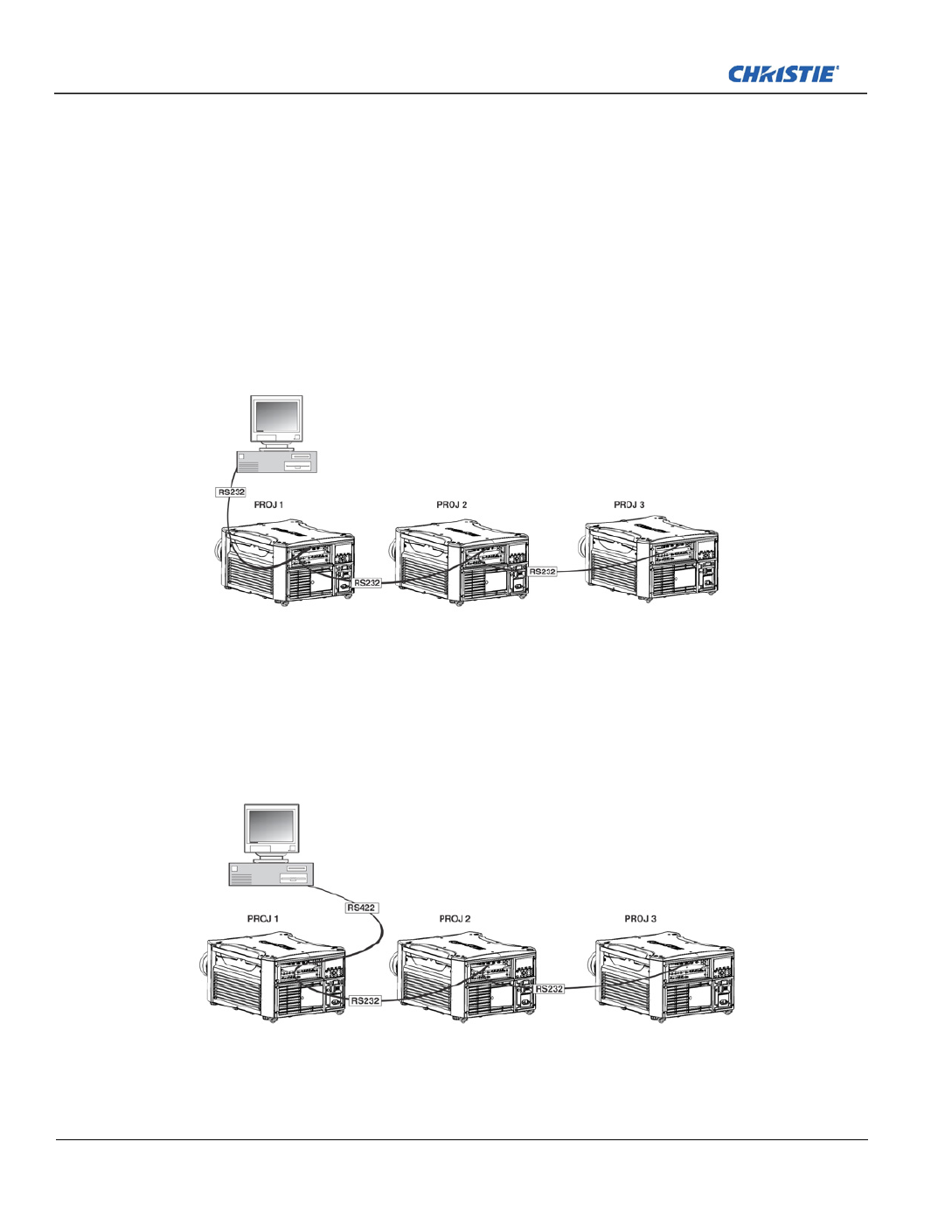
2-26 J Series 2.0, 2.4 and 3.0 kW User Manual
020-100707-03 Rev. 1 (02-2014)
Section 2: Installation and Setup
2.5.5 Ethernet Communications
See Section 3 Operation for further information about setting up and using a projector connected via Ethernet,
and the Serial Command document provided in the Dealer Section of the Christie Website, 020-100224-XX.
2.5.6 Connect Multiple Projectors
RS-232 Network: To connect multiple projectors in a network with serial communication:
1. Connect the controller source to the RS-232 IN connector of the first projector in the network.
2. Use another serial communication cable to connect one end to the RS-232 OUT connector and the other
end to the RS-232 IN connector of the next projector.
3. Continue this pattern of connection with all projectors in the network.
NOTE: The last projector in the network will only have a connection to the RS-232 IN connector.
Mixed Network: To control multiple projectors with a computer/controller having an RS-422 interface:
1. Set them all to the same baud rate as your RS-422 controller.
NOTE: You must enable this combination of RS-422 and RS-232 in the Communications menu. Set the
“ ”Network Routing option to “RS-232 and RS-422 Joined”, see Section 4 Web User Interface.
2. Chain the projectors together by connecting an RS-232 OUT (Null Cable) of the first projector (already
connected to the computer/controller) through the RS-422 port straight thru to an RS-232 IN on the next
projector in the chain. Continue connecting projectors in this manner until the last projector in the chain, so
that only the last projector has one unused port RS-232 OUT.

2-30 J Series 2.0, 2.4 and 3.0 kW User Manual
020-100707-03 Rev. 1 (02-2014)
Section 2: Installation and Setup
2.6 Projector Communications
2.6.1 Status LEDs
Looking from the back of the projector, the LEDs represent, from left to right; Lamp 1, Lamp 2, Power, and
Status. The LEDs will display the colors as shown below:
PROJECTOR STATE LEDS LED STATE
Hard Boot All All LEDs amber - means please wait
Standby Mode Lamp 1 and 2 Off - lamps are off
Power Amber - AC is present but projector is off or
standby
Shutter Green - shutter is open
Amber - shutter is closed
Warm-up (Powering ON from standby) All LEDs cycle green from left to right
Normal Operation Lamp 1 and 2 Amber - lamp time has expired and lamp should
be replaced
Power Green - projector is powered up and operating
normally
Shutter Green - shutter is open
Amber - shutter is closed
Cool-down All LEDs cycle amber from left to right
Error
Lamp 1 and 2
Amber - lamp time has expired and lamp should
be replaced
Flashing Red - lamp has malfunctioned
Power Flashing Red - error has occurred. Details are
displayed on the status display
Software Upgrade in progress All The pattern will alternate between:
Amber and Off
Lamp Regeneration in progress Lamp 1 and 2 Flashing Green - the lamp is being switched
off for its regeneration period to extend lamp life
(typically 15 minutes every 24 hours)
Power Green - on
-OR-
Amber - standby
Shutter Green - shutter is open
NOTE: A condition occurs on the first power on after a software upgrade, and is indicated by all the following:
•The Status LEDs are cycling green
•The LCD displays the warning “Image Processor Upgrading”
•The LED on the Image Processor card flashes green
•The Web page shows a warning that the Image processor card is upgrading.
When this occurs, the projector should not be AC power cycled and the Image Processor card should not be removed.

2-32 J Series 2.0, 2.4 and 3.0 kW User Manual
020-100707-03 Rev. 1 (02-2014)
Section 2: Installation and Setup
2.7.3 Analog BNC Input Card
This card accepts several types of sync modes. In 5-wire sync mode all 5 BNC connectors are used. If H and V
connectors are swapped, this card will still operate normally. An analog graphic source such as a VGA from a
PC can be connected. The card can operate in 4-wire sync mode, which accommodates 4-wire RGBC sources.
The composite sync cable can be connected to either the H/C BNC or the V BNC. The card supports 3-wire
RGB or YPbPr sync modes, sometimes called sync-on-Green (SOG). In this mode the H/C and V connectors
are not used. The sync is connected to the Green/Y BNC connector. This card offers no loop out capability.
There are 2 LED’s on the module faceplate. PWR indicates power has been applied and the card is initialized,
signal indicates a valid signal has been detected.
2.7.4 Dual 3G/HD/SD-SDI Input Card
This card accepts both standard-definition (SD) and high-definition (HD) serial-digital-interface (SDI) signals
from 1 of 2 standard-definition (SD) or high-definition (HD) 3GHz SDI sources. Both single-link HD and
dual-link HD signals are accepted. The card has two SD/HD-SDI outputs, each of which is “loop through” for
its respective input. There are 3 LEDs on the module faceplate. PWR indicates power has been applied and the
card is initialized, and the two signal LEDs indicate a valid signal ha the respective input. s been detected on
2.7.5 Dual Link DVI Input Card
This card accepts a single DVI signal with or without High-Bandwidth Digital Content Protection (HDCP)
video signal over a DVI-I connector and analog video signals over the DVI-I or 15-pin VGA connector. The
module can simultaneously support a digital signal on the DVI input and an analog signal on the VGA port,
however it does not support 2 analog signals at the same time. There are 4 LEDs on the module faceplate. PWR
indicates power is applied and the card is initialized, and the other 3 on the right side of the corresponding
connectors indicate that a valid signal has been detected.

2-34 J Series 2.0, 2.4 and 3.0 kW User Manual
020-100707-03 Rev. 1 (02-2014)
Section 2: Installation and Setup
2.7.8 Twin DisplayPort Input Card
The Twin DisplayPort Input card accepts Display Port 1.1a inputs from one or two DisplayPort sources. The
card has two DisplayPort outputs, each of which is loop through for its respective input (loop through of
encrypted content is not supported). Five LEDs are on the card faceplate. The PWR on the left side indicates
power is applied and the card is initialized. The LEDs on the right side of the corresponding connectors
indicate a valid signal is detected. In the case of the output, the LED indicates a signal is currently being looped
out.
2.7.9 Connect Tiled Projectors
Wiring Requirements
A distribution box or digital signal switcher may be used to feed the same video signal to all the units of the
tiling array.
FIGURE 2-5 USE OF OX DISTRIBUTION B
Christie loop-through may be used to set up a tiling array (see Figure 2-5 to Figure 2-10). The system allows
wiring (providing the HDCP requirement is met) when HDCP is used by the source. The cascade level of
devices must be no more than 7 levels deep.
NOTE: If single wire loop-through is used (See Figure 2-9), then PIP is not supported.
The wiring diagrams are provided to:
• Meet the HDCP requirement,
• Minimize the length of HDMI cables to be used, and
(ROW 1, COL 1) (ROW 1, COL 2) (ROW 1, COL 3)
From Source
Distribution Box
Produkt Specifikationer
| Mærke: | Christie |
| Kategori: | Beamer |
| Model: | Roadster S Plus 22K-J |
Har du brug for hjælp?
Hvis du har brug for hjælp til Christie Roadster S Plus 22K-J stil et spørgsmål nedenfor, og andre brugere vil svare dig
Beamer Christie Manualer

3 Januar 2025
17 December 2024
17 December 2024
17 December 2024
17 December 2024
24 September 2024
23 September 2024
23 September 2024
26 August 2024
26 August 2024
Beamer Manualer
- Beamer Acer
- Beamer Sony
- Beamer Canon
- Beamer Samsung
- Beamer Panasonic
- Beamer Philips
- Beamer Lenco
- Beamer OK
- Beamer Derksen
- Beamer LG
- Beamer Mitsubishi
- Beamer Sharp
- Beamer Epson
- Beamer Technaxx
- Beamer Smart
- Beamer HP
- Beamer Sanyo
- Beamer D-Link
- Beamer Asus
- Beamer Toshiba
- Beamer Pyle
- Beamer Klarstein
- Beamer Kodak
- Beamer InFocus
- Beamer Lenovo
- Beamer Adj
- Beamer Optoma
- Beamer Da-Lite
- Beamer Hama
- Beamer Auna
- Beamer Casio
- Beamer Hisense
- Beamer Maxell
- Beamer Smartwares
- Beamer Blaupunkt
- Beamer JVC
- Beamer Leica
- Beamer Hitachi
- Beamer Medion
- Beamer 3M
- Beamer BenQ
- Beamer Acco
- Beamer Anker
- Beamer Aiptek
- Beamer Viewsonic
- Beamer Dell
- Beamer Vivitek
- Beamer Polaroid
- Beamer Ricoh
- Beamer NEC
- Beamer Stairville
- Beamer OKI
- Beamer Reflecta
- Beamer Nebula
- Beamer Salora
- Beamer Vogel's
- Beamer Overmax
- Beamer RCA
- Beamer Prixton
- Beamer Renkforce
- Beamer Eurolite
- Beamer Yaber
- Beamer XGIMI
- Beamer GPX
- Beamer Dahua Technology
- Beamer Cameo
- Beamer Kogan
- Beamer Barco
- Beamer Planar
- Beamer Speaka
- Beamer ASK Proxima
- Beamer Eiki
- Beamer Naxa
- Beamer Vankyo
- Beamer Emtec
- Beamer Promethean
- Beamer Odys
- Beamer Laserworld
- Beamer Ibm
- Beamer La Vague
- Beamer Tzumi
- Beamer EKO
- Beamer MicroVision
- Beamer Elite Screens
- Beamer Celexon
- Beamer Fun Generation
- Beamer PLUS
- Beamer Futurelight
- Beamer Varytec
- Beamer Ultimea
- Beamer Dracast
- Beamer Dukane
- Beamer Dream Vision
- Beamer Knoll
- Beamer DTS
- Beamer Touchjet
- Beamer Boxlight
- Beamer AAXA Technologies
- Beamer Miroir
- Beamer Mimio
- Beamer AWOL Vision
- Beamer Smart Tech
- Beamer Atlantis Land
- Beamer KickAss
- Beamer Microtek
- Beamer Panamorph
Nyeste Beamer Manualer

5 Marts 2025
5 Marts 2025

30 Januar 2025
30 Januar 2025
30 Januar 2025
30 Januar 2025
30 Januar 2025
30 Januar 2025

29 Januar 2025
13 Januar 2025