Tenda AP5 Manual
Tenda
Adgangspunkt
AP5
Læs nedenfor 📖 manual på dansk for Tenda AP5 (141 sider) i kategorien Adgangspunkt. Denne guide var nyttig for 10 personer og blev bedømt med 4.5 stjerner i gennemsnit af 2 brugere
Side 1/141

300Mbps Wireless N Access Point
User Guide

i
Copyright Statement
© 2019 Shenzhen Tenda Technology Co., Ltd. All rights reserved.
is a registered trademark legally held by Shenzhen Tenda Technology Co., Ltd. Other
brand and product names menoned herein are trademarks or registered trademarks of their
respecve holders. Copyright of the whole product as integraon, including its accessories and
soware, belongs to Shenzhen Tenda Technology Co., Ltd. No part of this publicaon can be
reproduced, transmied, transcribed, stored in a retrieval system, or translated into any language in
any form or by any means without the prior written permission of Shenzhen Tenda Technology Co.,
Ltd.
Disclaimer
Pictures, images and product specicaons herein are for references only. To improve internal
design, operaonal funcon, and/or reliability, Tenda reserves the right to make changes to the
products without obligaon to nofy any person or organizaon of such revisions or changes. Tenda
does not assume any liability that may occur due to the use or applicaon of the product described
herein. Every eort has been made in the preparaon of this document to ensure accuracy of the
contents, but all statements, informaon and recommendaons in this document do not constute
a warranty of any kind, express or implied.

ii
Preface
Thank you for choosing Tenda. Please read this user guide before you start.
Convenons
This user guide applies to the following access points AP4 and AP5. AP4 is used for illustraons :
here unless otherwise specied. The contained images and UI screenshots are subject to the actual
products.
Product model
Descripon
AP4
300Mbps Wireless N Access Point
AP5
300Mbps Wireless N Access Point
The typographical elements that may be found in this document are dened as follows.
Item
Presentaon
Example
Cascading menus
>
System Live Users >
Parameter and value
Bold
Set . User Name to Tom
Variable
Italic
Format : : : : : : XX XX XX XX XX XX
UI control
Bold
On the page, click the buon. Policy OK
Message
“ ”
The Success message appears. “ ”
The symbols that may be found in this document are dened as follows.
Symbol
Meaning
This format is used to highlight informaon of importance or special interest.
Ignoring this type of note may result in ineecve conguraons, loss of data or
damage to device.
This format is used to highlight a procedure that will save me or resources.

iii
Acronyms and Abbreviaons
Acronym or Abbreviaon
Full Spelling
AP
Access Point
APSD
Automac Power Save Delivery
ARP
Address Resoluon Protocol
AES
Advanced Encrypon Standard
CCQ
Client Connecon Quality
DHCP
Dynamic Host Conguraon Protocol
DNS
Domain Name System
DDNS
Dynamic Domain Name Server
DTIM
Delivery Trac Indicaon Message
GMT
Greenwich Mean Time
IP
Internet Protocol
LAN
Local Area Network
MAC
Media Access Control
OS
Operang System
PoE
Power Over Ethernet
PVID
Port-based VLAN ID
RADIUS
Remote Authencaon Dial In User Service
RAM
Random Access Memory
RSSI
Received Signal Strength Indicator
RX
Receive
SSID
Service Set Idener
TCP
Transmission Control Protocol

iv
Acronym or Abbreviaon
Full Spelling
TKIP
Temporal Key Integrity Protocol
TX
Transmit
UDP
User Datagram Protocol
UI
User Interface
VID
Virtual Local Area Network Idencaon
VLAN
Virtual Local Area Network
WAN
Wide Area Network
WEP
Wired Equivalent Privacy
WISP
Wireless Internet Service Provider
WLAN
Wireless Local Area Networks
WMM
Wi-Fi mul-media
WPA- PSK
WPA-Preshared Key
WPA
Wi-Fi Protected Access

v
Getng more documents
If you want to get more documents of the device, visit www.tendacn.com and search for the
corresponding product model. The related documents are listed as below:
Document
Descripon
Quick Installaon Guide
It introduces how to set up the device quickly for internet access, the
descripons of LED indicators, ports, and buons, FAQ, statement informaon,
and so on.
User Guide
It introduces how to set up more funcons of the device for more requirements,
including all funcons on the web UI of the device.
Data Sheet
It introduces the basic informaon of the device, including product overview,
selling points, and specicaons.
Technical Support
If you need more help, contact us by any of the following means. We will be glad to assist you as
soon as possible.
Hotline
Global: ( 755-27657180 86)
Toll Free: Mon - Fri 9 am - 6 pm
(China Time Zone)
Email
support@tenda.com.cn
United States: 1-800- -5892 570
Toll Free: Daily-9am to 6pm P ST
Canada: 1-888- -8966 998
Toll Free: Mon - Fri 9 am - 6 pm PST
Hong Kong: 00852-81931998
Toll Free: Mon - Fri 9 am - 6 pm
(China Time Zone)

vi
Contents
1 Login ........................................................................................................................................ 1
1.1 Login ......................................................................................................................................... 1
1.2 Logout ...................................................................................................................................... 3
2 Web UI 4 ....................................................................................................................................
2.1 Web UI layout ........................................................................................................................... 4
2.2 Common buons ..................................................................................................................... 5
3 Status ...................................................................................................................................... 6
3.1 System status 6...........................................................................................................................
3.2 Wireless status ......................................................................................................................... 9
3.3 Stascs ................................................................................................................................. 11
4 Quick setup ...........................................................................................................................16
4.1 AP mode ................................................................................................................................. 16
4.2 Client mode ............................................................................................................................ 22
4.3 Universal repeater mode ....................................................................................................... 29
4.4 WISP mode ............................................................................................................................. 38
4.5 Client + AP mode .................................................................................................................... 46
4.6 Router mode .......................................................................................................................... 53
5 Network ................................................................................................................................ 59
5.1 LAN setup ............................................................................................................................... 59
5.2 MAC clone .............................................................................................................................. 66
5.3 DHCP server ........................................................................................................................... 68
5.4 ............................................................................................................................. DHCP client 70
5.5 VLAN sengs ......................................................................................................................... 71
6 Wireless . ................................................................................................................................ 76
6.1 Basic ....................................................................................................................................... 76
6.2 Advanced ................................................................................................................................ 88
6.3 Access control ........................................................................................................................ 91

vii
7 Advanced ..............................................................................................................................94
7.1 LAN rate .................................................................................................................................. 94
7.2 Diagnose ................................................................................................................................. 95
7.3 Bandwidth control .................................................................................................................99
7.4 Port forwarding .................................................................................................................... 103
7.5 MAC lt er ............................................................................................................................. 108
7.6 Network service ................................................................................................................... 112
8 Tools .................................................................................................................................... 124
8.1 Date & me .......................................................................................................................... 124
8.2 Maintenance ........................................................................................................................ 126
8.3 Account ................................................................................................................................ 131
8.4 System log ............................................................................................................................ 132
Appendix .................................................................................................................................... 133
Default parameters .................................................................................................................... 133

2
The following page appears.
If you want to log in to the AP in AP mode, perform the following procedure.
Step 1 Connect a computer to the LAN1 port of the AP using an Ethernet cable.
Step 2 Set the IP address of the computer to ( ranges from 1 to 253), and subnet 192.168.0.X X
mask to . 255.255.255.0
Step 3 Start a web browser on the computer, and visit . Enter your user name and 192.168.0.254
password you set, and click . Login
----End
If you want to log in to the in Client mode, Universal Repeater mode, or Client + AP modeAP ,
perform the following procedure.
Step 1 Connect a computer to the LAN1 port of the AP using an Ethernet cable.
Step 2 Start a web browser on the computer, and visit the IP address of the AP you set before.
Enter your user name and password you set, and click . Login
If you forget the IP address you set for the AP, you can log in to the web UI of the upstream AP and check
its DHCP client list.
----End
If you want to log in to the in Router mode or WISP mode, perform the following AP
procedure.
Step 1 Connect a computer to the LAN1 port of the AP using an Ethernet cable.
Step 2 Start a web browser on the computer, and visit the IP address of the AP you set before.
Enter your user name and password you set, and click . Login
If you forget the IP address you set for the AP, you check the gateway IP address of the computer, and
use this IP address for login.
----End

3
1.2 Logout
The logs you out when you: AP
− Click the button on the upper-right corner of the web UI. Logout
− Close the web browser.
− Perform no operaon within the login meout interval (default: 5 minutes). You can
change the login meout interval on the Advanced Network Service > page.

4
2 Web UI
2.1 Web UI layout
The web UI of the device is composed of 4 parts, including the level-1 navigaon tree, level-2
navigaon tree, tab page area, and conguraon area. See the following gure.
No.
Name
Descripon
❶
L -1 navigaon tree evel
The navigaon bars and tab pages display the funcon menu of the
device. When you select a funcon in navigaon bar, the
conguraon of the funcon appears in the conguraon area.
❷
L -2 navigaon tree evel
❸
Tab page area
❹
Conguraon area
It enables you to view and modify conguraon.
1
2
3
4

5
2.2 Common buons
The following table describes the common buons available on the web UI.
Common Buons
Descripon
It is used to update the content of the current page.
It is used to save the conguraon on the current page and enable the conguraon
to take eect.
It is used to go back to the original conguraon without saving the conguraon on
the current page.
It is used to view help informaon corresponding to the sengs on the current
page.

6
3 Status
This module includes three parts: system status, wireless status stascs, and .
3.1 System status
On the System Status page, you can view the system status here.
To access the page, log in to the web UI of the device, and choose . Status
In mode, mode, AP Client Universal Repeater Client + AP mode, or mode, the system status is
shown as follows:
Parameters descripon
Name
Descripon
Device Name
It species the name of this device.
A unique device name helps you manage mulple devices that are of the same
model on LAN easily. To modify the device name, go to Network > LAN Setup
page. You are allowed to modify only when the device works in AP, Client,
Universal Repeater Client + AP , or mode.
Upme
It species the me that has elapsed since the device was started last me.
System Time
It species the current system me of this device.
Hardware Version
It species the hardware version number of this device.

7
Name
Descripon
RAM
Random Access Memory. It species the memory usage of this device.
WLAN MAC Address
It species the MAC address of the WiFi network of this device.
PoE LAN/LAN Speed
It species connecon status of LAN port. It includes connecon rate and duplex
mode.
LAN IP Address
It species the IP address (also called login or management IP address) of this
device. By default, it is . 192.168.0.254
Firmware Version
It species the system soware version number of this device.
CPU
Central Processing Unit.
It species the CPU usage of this device.
LAN MAC Address
It species the MAC address of LAN ports of this device.
In or WISP Router mode, the system status is shown as follows:

8
Parameters descripon
Name
Descripon
Connecon Type
It species the internet connecon type of this device.
Connecon Status
It species the connecon status of WAN port of this device.
WAN IP Address
It species the IP address of WAN port of this device.
Default Gateway
It species the default gateway address of this device.
Primary DNS Server
It species the IP address of primary DNS server of this device.
Secondary DNS Server
It species the IP address of secondary DNS server of this d evice.
9
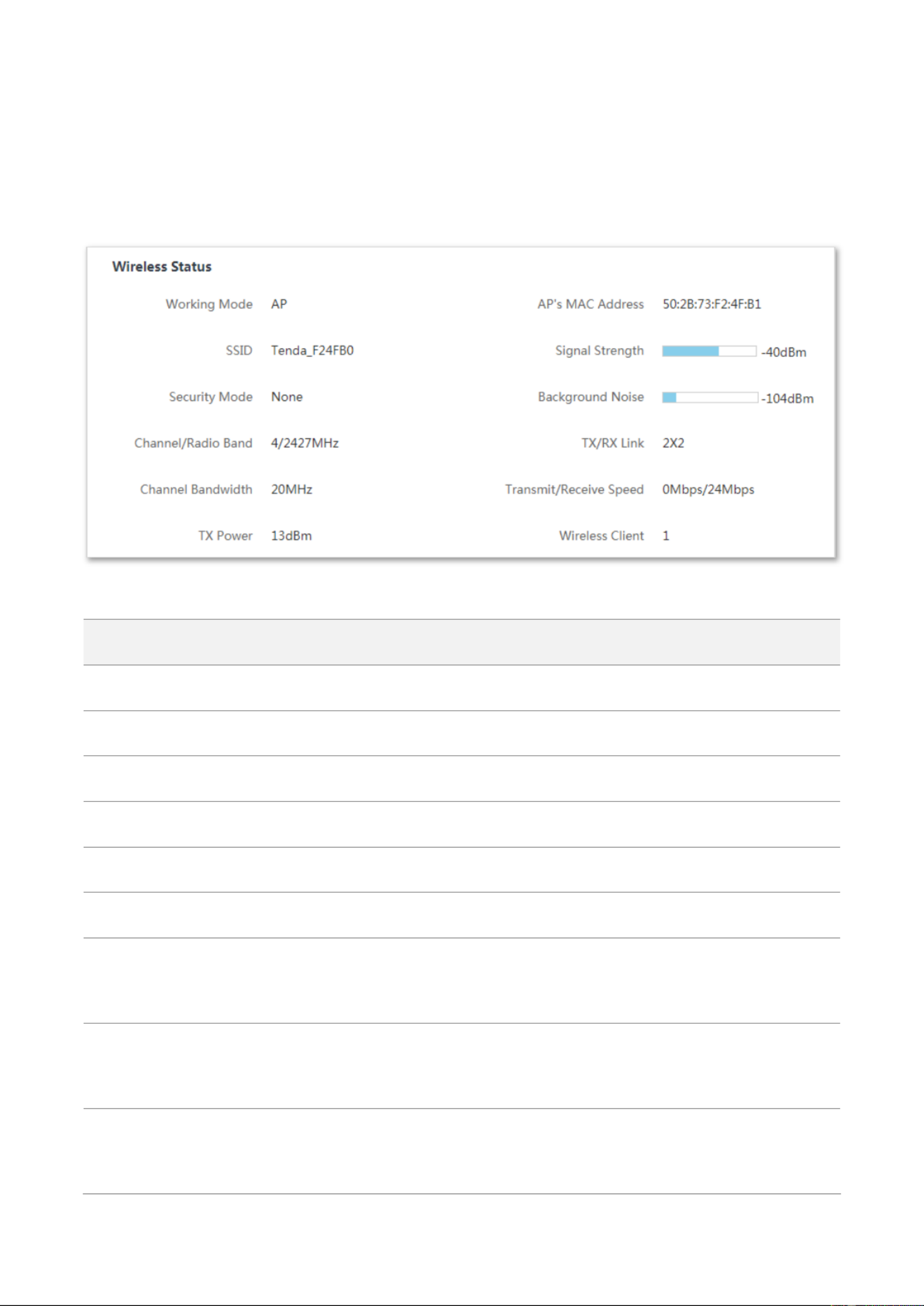
3.2 Wireless status
On the Wireless Status pa , you can view wireless status here, including working mode, SSID, ge
security mode, and so on.
To access the page, log in to the web UI of the device, and choose Status.
Parameters descripon
Name
Descripon
Working Mode
It species the working mode the device operates.
SSID
It species the WiFi name of this device. In Client mode, it displays N/A.
Security Mode
It species the security mode of the WiFi network of this device.
Channel/Radio Band
It species the channel and frequency band the device operates.
Channel Bandwidth
It species the channel bandwidth of this device.
TX Power
It species the transmit power of this device.
AP’s MAC Address
I modes, it displays the MAC n Client, Universal Repeater, WISP or Client + AP
address of peer AP to which this device bridged. I mode, it displays n AP or Router
No Peer AP if the device works.
Signal Strength
I mode, it displays the signal strength of the rst device connected to n AP or Router
the WiFi network of the device. I n Client, Universal Repeater, WISP or Client + AP
mode, it displays the received signal strength from peer AP.
Background Noise
It species the strength of ambient radio interference. Larger absolute value
indicates less interference. For example, -95 dBm indicates less interference than
that of -75 dBm.

10
Name
Descripon
TX/RX Link
It species the number of spaal streams the device is transming or receiving.
Transmit/Receive Speed
It species the wireless transming/receiving rate.
I mode: it displays the transming/receiving rate of the rst client n AP or Router
connected to the WiFi network of this device.
In mode: it displays Client, Universal Repeater, WISP or Client + AP
transming/receiving rate of this device.
Wireless Client
It species the number of wireless clients connected to this device. In mode, it Client
displays . N/A

11
3.3 Stascs
On the Statiscs page, you can view stascs informaon here, including throughput, wireless
client interface ARP table roung table, , and .
To access the page, log in to the web UI of the device, and choose . Status
3.3.1 Throughput
The line charts visually show the real-me transmitng and receiving trac of WLAN and LAN ports
of the device.
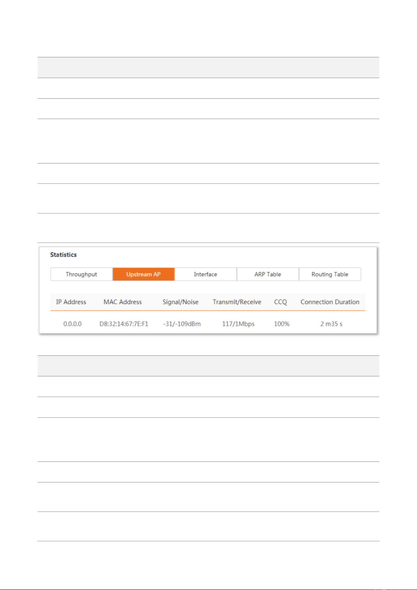
3.3.2 Wireless client/Upstream AP
This module diers depending on the working mode of the device.
-In or AP Router mode, it displays informaon of connected wireless clients.
-In , Client Universal Repeater WISP Client + AP , or mode, it displays informaon of upstream AP.
12
Parameters descripon
Name
Descripon
IP Address
It species the IP address of the corresponding wireless client.
MAC Address
It species the MAC address of the corresponding wireless client.
Signal/Noise
Signal: It species the WiFi signal strength of the corresponding wireless client.
Noise: It species the ambitus interference signal and electromagnec
interference strength.
Transmit/Receive
It species the transming and receiving rate of the corresponding client.
CCQ
It species the connecon quality of the corresponding client Higher percentage .
indicates beer connecon quality.
Connecon Duraon
It species the me that has elapsed since the wireless client is connected to the
WiFi network of the device last me.
Parameters descripon
Name
Descripon
IP Address
It species the IP address of the upstream device.
MAC Address
It species the MAC address of the upstream device.
Signal/Noise
Signal: It species the WiFi signal strength of the corresponding wireless client.
Noise: It species the ambitus interference signal and electromagnec
interference strength.
Transmit/Receive
It species the transming and receiving rate of the upstream device.
CCQ
It species the connecon quality of the upstream device. Higher percentage
indicates beer connecon quality.
Connecon Duraon
It species the me that has elapsed since this device is connected to the upstream
AP last me.

13
3.3.3 Interface
On It displays the IP address, MAC address and trac informaon of the interfaces of the device.
Parameters descripon
Name
Descripon
Interface
It species the interface type that packets passes through, including LAN, Bridge,
and WLAN interfaces.
IP Address
It displays the IP addresses of wired interface, bridge interface, and WLAN interface.
MAC Address
It displays the MAC addresses of interface. an
Received Packets
It displays the received and transmied packets of the interface.
Transmied Packets
Receive Error
It displays the number of error packets received/transmied by the interface.
Transmit Error
14
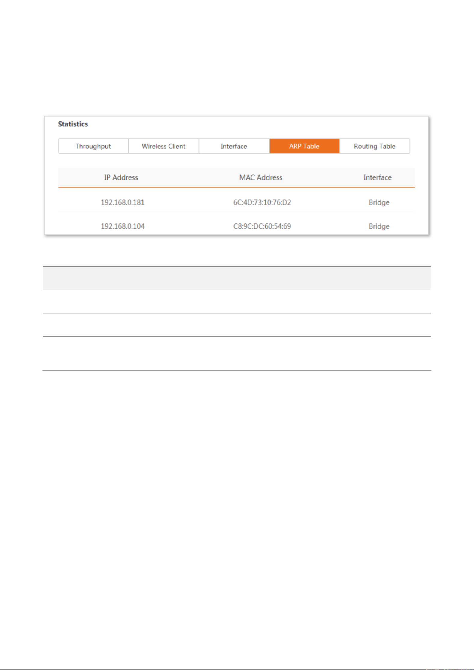
3.3.4 ARP table
ARP (Address Resoluon Protocol) is a network layer protocol used to convert an IP address into a
physical address. The ARP table displays the IP address and its corresponding MAC address the
device visits, and the interface the packets pass through.
Parameters descripon
Name
Descripon
IP Address
It species the IP address of the host in the APR table.
MAC Address
It species the MAC address corresponding to the IP address.
Interface
It species the interface used to communicate with the host, including LAN, WLAN
and bridge interfaces.

15
3.3.5 Roung table
It species the desnaon networks that the device can access.
To access the page, log in to the web UI of the device, and choose Status Roung Table, then in
Stascs part.
Parameters descripon
Name
Descripon
Desnaon Network
It species the IP address of the desnaon network.
Subnet Mask
It species the subnet mask of the desnaon network.
Next H op
It species the IP address of entrance of the next hop route when the packets egress
from the interface of the device. 0.0.0.0 indicates that the desnaon network is the
network which is directly connected to the interface.
Interface
It species the interface that the packets egress.

16
4 Quick setup
This module enables you to quickly congure the device or change the working mode of the device
to deploy your WiFi network.
This AP supports , , AP Client Universal Repeater WISP Client + AP Router, , , and modes.
4.1 AP mode
4.1.1 Overview
In mode, this device connects to a wired network, and provides a WiFi network for wireless AP
clients.
Network requirement: You want to transform your wired network to a wireless one for your
wireless devices to access the internet.
Conguraon procedure of setng AP mode
Step 1 Log in to the web UI of the AP and choose to enter the conguraon page. Quick Setup
Step 2 Select mode and click . AP Next
AP mode
Modem router

17
Step 3 Set an , (WPA2-PSK is recommended) and SSID Security Mode Key Next, and click .
Step 4 Note down the and SSID Key and keep them well. Then click Save.
----End
*
*
*

18
Wait unl the device completes reboong to apply your setngs.
Then connect your WiFi-enabled devices using the (WiFi network name) and SSID Key (WiFi
password) you set and enjoy the internet access.
You can navigate to to view and modify the wireless informaon later. Wireless > Basic
Parameters descripon
Parameter
Descripon
Working modes
It species the working mode of this device.
AP mode: In this mode, the device creates a WiFi network based on the current wired
network.
SSID
It species the WiFi name of this device.
Channel
It species the operang channel of this device.
Auto (Default): It indicates that the device automacally adjusts its operang channel
according to the ambient environment.
Security Mode
It species the security mode of the WiFi network, including: None, WPA-PSK,
WPA2- Mixed WPA/WPA2-PSK, and PSK.
Clicking the hyperlink navigates you to the elaborated descripon of the
corresponding security mode.
Encrypon
Encrypon Algorithm
It species the encrypon method of the WiFi network.
AES: It indicates the Advanced Encrypon Standard.
TKIP TKIP: It indicates the Temporal Key Integrity Protocol. If is used, the maximum
wireless throughput of the AP is limited to 54 Mbps.
TKIP&AES TKIP AES: It indicates that both and encrypon algorithms are supported.
Wireless clients can connect to the WiFi network corresponding to the selected SSID
using . TKIP or AES
Encrypon Mode
Key
It species the WiFi password of the WiFi network.
4.1.2 Example of mode AP
Network requirement
You have several WiFi-enabled devices at your home, such as smart phones, tablets, smart speakers
etc. But the modem router at your home can only provide internet access to wired devices. Now
you want to establish a WiFi network for these wireless devices.

20
Step 3 Select mode and click . AP Next
Step 4 Set an SSID, which is Tenda_F24FB0 in this example, (WPA2-PSK is Security Mode
recommended) and Key Next, and click .
Step 5 Note down the and SSID Key and keep them well. Then click Save.
*
*
*

23
If you cannot nd any SSID from the list, choose enable the wireless funcon. Then Wireless > Basic and
try again.
Step 4 Enter the WiFi password of your upstream network in the Key text box, and click . Next
Step 5 Set the IP address to an unused IP address belonging to the same network segment as that
of the upstream AP. For example, if the IP address of the upstream AP is 192.168.0.1, you
can set the IP address of this device to 192.168.0. ( ranges from 2 to 254). Then click X X
Next.
*
24
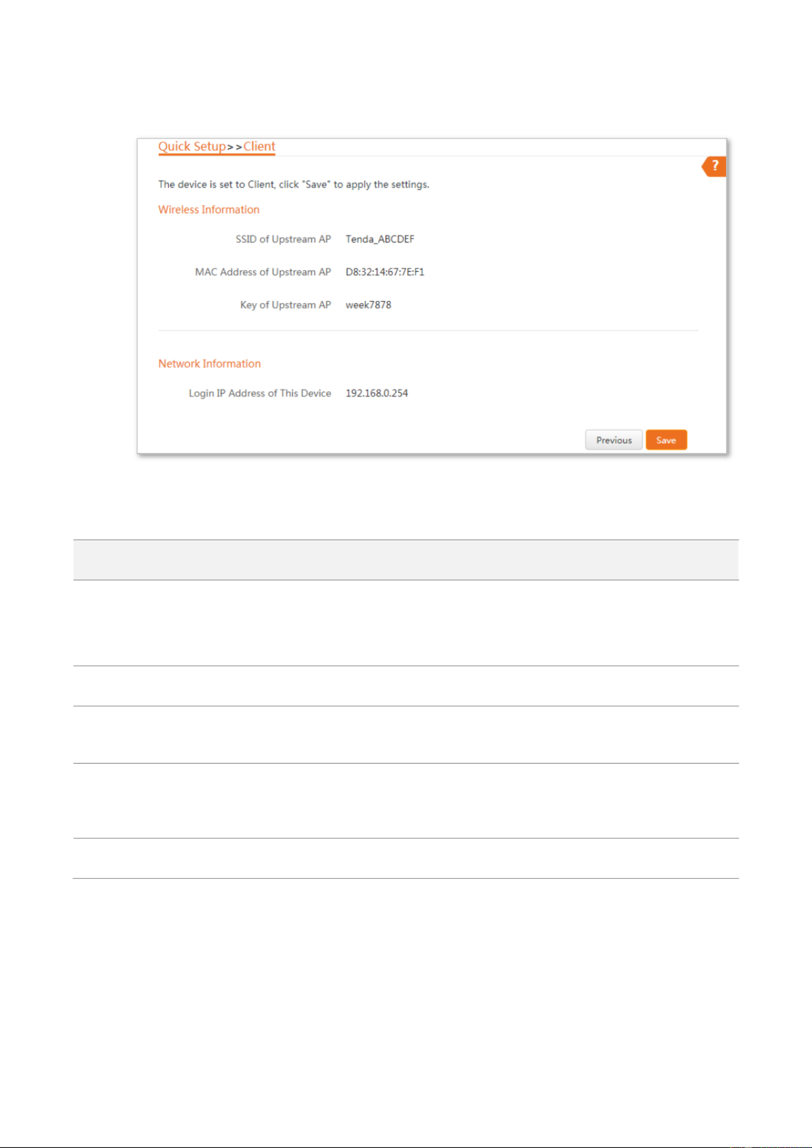
Step 6 Check whether the SSID you selected and WiFi password you enter are correct. Then ed
click Save.
----End
Parameters descripon
Parameter
Descripon
Working modes
It species the working mode of this device.
Client mode In this mode, the device works as a wireless adapter to connect to the :
WiFi network of upstream AP, and does not provide WiFi network.
Upstream AP
It species the SSID (WiFi name) of the upstream AP.
Channel
It species the operang channel of the device, which is the same as the upstream AP
to be bridged.
Security Mode
It species the security mode of the WiFi network to be bridged. It will be automacally
populated when you select an SSID to bridge. If the WiFi network to be bridged has a
WiFi key, you need to enter the password manually.
Key
It species the WiFi key of the upstream AP.

28
Step 6 Check whether the SSID you select and WiFi password you enter are correct. Then click
Save.
----End
Verification
The computer connected to the LAN port of the AP can access the internet now.
In client mode, the two Ethernet ports are both LAN ports.

30
Step 4 Wait until the LED indicator of the AP turns to solid on, which indicates that the AP BRIDGE
bridges to your existing WiFi router successfully.
Step 5 Relocate the AP. Place it:
− In a high and open area.
− Within the WiFi coverage range of your existing WiFi router.
− In the middle place between your existing WiFi router and the WiFi dead zone.
----End
The AP’s WiFi network name: Same as that of your existing WiFi router.
The AP’s WiFi password: Same as that of your existing WiFi router.
Now you can connect your WiFi-enabled clients to the AP’s WiFi network and enjoy internet access.
Option 2: Using the web UI
Configuration procedure of setting Universal Repeater mode
Step 1 Place the AP near your existing WiFi router, and power it on.
Step 2 Log in to the web UI of the AP and choose to enter the configuration page. Quick Setup
Step 3 Select Universal Repeater Next, and click .
Produkt Specifikationer
| Mærke: | Tenda |
| Kategori: | Adgangspunkt |
| Model: | AP5 |
| Bredde: | 148 mm |
| Dybde: | 31.5 mm |
| Højde: | 146.2 mm |
| Produktfarve: | Sort |
| Opbevaringstemperatur (T-T): | -30 - 70 °C |
| Relativ luftfugtighed ved drift (H-H): | 10 - 90 % |
| Relativ luftfugtighed ved opbevaring (H-H): | 5 - 90 % |
| Ethernet LAN-porte (RJ-45): | 2 |
| Driftstemperatur (T-T): | -10 - 45 °C |
| Ethernet LAN-datahastigheder: | 10, 100 Mbit/s |
| Sikkerhedsalgoritmer: | 64-bit WEP, 128-bit WEP, WPA, WPA2, WPA2-PSK |
| Hurtig start guide: | Ja |
| Certificering: | FCC, CE, VoC, Rohs |
| Placering: | Table, Wall |
| Netværksstandarder: | IEEE 802.11b, IEEE 802.11g, IEEE 802.11n |
| DC-in-stik: | Ja |
| DHCP-klient: | Ja |
| DHCP-server: | Ja |
| Understøttede netværksprotokoller: | http/https |
| Antenner, antal: | 3 |
| Knap til nulstilling: | Ja |
| LED-indikatorer: | LAN, System, WLAN, WPS |
| Udgangsspænding: | 12 V |
| Udgangsstrøm: | 1 A |
| AC-adapter inkluderet: | Ja |
| Harmoniseret systemkode (HS): | 85176990 |
| Maksimal indendørs rækkevidde: | 50 m |
| Antal brugere: | 20 bruger(e) |
| Frekvensbånd: | 2.4 - 2.483 GHz |
| Intern: | Ingen |
| Maksimal dataoverførselshastighed: | 300 Mbit/s |
| Wi-Fi-datahastighed (maks.): | 300 Mbit/s |
| Firmware kan opgraderes: | Ja |
| Strøm over Ethernet (PoE): | Ja |
| 2.4 GHz: | Ja |
| 5 GHz: | Ingen |
| Antal SSID understøttet: | 8 |
| Niveau for antennestyrke (maks.): | 5 dBi |
| Service Set Identifier (SSID) funktioner: | SSID-udsendelse til/fra |
| Transmissionseffekt: | 23 dBmW |
| Antennestik type: | RP-SMA |
| PoE-adapter inkluderet: | Ja |
Har du brug for hjælp?
Hvis du har brug for hjælp til Tenda AP5 stil et spørgsmål nedenfor, og andre brugere vil svare dig
Adgangspunkt Tenda Manualer

31 August 2024
31 August 2024
16 August 2024
6 August 2024
8 Februar 2024
2 December 2023
25 Oktober 2023
9 Oktober 2023
25 Juli 2023
7 Marts 2023
Adgangspunkt Manualer
- Adgangspunkt Bosch
- Adgangspunkt Aruba
- Adgangspunkt Netis
- Adgangspunkt Moog
- Adgangspunkt TP-Link
- Adgangspunkt HP
- Adgangspunkt D-Link
- Adgangspunkt Asus
- Adgangspunkt AVM
- Adgangspunkt Planet
- Adgangspunkt Belkin
- Adgangspunkt Edimax
- Adgangspunkt Black Box
- Adgangspunkt DataVideo
- Adgangspunkt TRENDnet
- Adgangspunkt Honeywell
- Adgangspunkt Buffalo
- Adgangspunkt Linksys
- Adgangspunkt Cisco
- Adgangspunkt Huawei
- Adgangspunkt Netgear
- Adgangspunkt Totolink
- Adgangspunkt Digitus
- Adgangspunkt Zebra
- Adgangspunkt Techly
- Adgangspunkt Dell
- Adgangspunkt Alcatel-Lucent
- Adgangspunkt LevelOne
- Adgangspunkt ZyXEL
- Adgangspunkt Fortinet
- Adgangspunkt LigoWave
- Adgangspunkt EQ3
- Adgangspunkt Ubiquiti Networks
- Adgangspunkt EnGenius
- Adgangspunkt Devolo
- Adgangspunkt Grandstream
- Adgangspunkt Renkforce
- Adgangspunkt Mikrotik
- Adgangspunkt Eminent
- Adgangspunkt Hercules
- Adgangspunkt V7
- Adgangspunkt Amer Networks
- Adgangspunkt Mercku
- Adgangspunkt EQ-3
- Adgangspunkt Vimar
- Adgangspunkt Dahua Technology
- Adgangspunkt Speco Technologies
- Adgangspunkt StarTech.com
- Adgangspunkt Draytek
- Adgangspunkt Crestron
- Adgangspunkt Lindy
- Adgangspunkt Lancom
- Adgangspunkt Sitecom
- Adgangspunkt AMX
- Adgangspunkt Homematic IP
- Adgangspunkt Intellinet
- Adgangspunkt Kingston
- Adgangspunkt Steren
- Adgangspunkt Media-Tech
- Adgangspunkt Moxa
- Adgangspunkt Allnet
- Adgangspunkt Allied Telesis
- Adgangspunkt Airlive
- Adgangspunkt Macally
- Adgangspunkt Hawking Technologies
- Adgangspunkt INCA
- Adgangspunkt Advantech
- Adgangspunkt Silex
- Adgangspunkt SMC
- Adgangspunkt Cambium Networks
- Adgangspunkt CradlePoint
- Adgangspunkt FlyingVoice
- Adgangspunkt Extreme Networks
- Adgangspunkt Aerohive
- Adgangspunkt Bountiful
- Adgangspunkt WatchGuard
- Adgangspunkt NUVO
- Adgangspunkt Cudy
- Adgangspunkt IP-COM
- Adgangspunkt Mach Power
- Adgangspunkt Syscom
- Adgangspunkt Meru
- Adgangspunkt Amped Wireless
- Adgangspunkt 3Com
- Adgangspunkt Ruckus Wireless
- Adgangspunkt Bintec-elmeg
- Adgangspunkt Brocade
- Adgangspunkt ICC
- Adgangspunkt Insteon
- Adgangspunkt Juniper
- Adgangspunkt Comtrend
- Adgangspunkt Premiertek
- Adgangspunkt Atlantis Land
- Adgangspunkt Mojo
- Adgangspunkt Luxul
- Adgangspunkt Peplink
Nyeste Adgangspunkt Manualer

5 April 2025
20 Marts 2025

15 Januar 2025
13 Januar 2025
13 Januar 2025
13 Januar 2025
12 Januar 2025
30 December 2025

26 December 2024
23 December 2024